Tool bit

Last updated

In machining, a tool bit is a non-rotary cutting tool used in metal lathes, shapers, and planers. Such cutters are also often referred to by the set-phrase name of single-point cutting tool, as distinguished from other cutting tools such as a saw or water jet cutter. The cutting edge is ground to suit a particular machining operation and may be resharpened or reshaped as needed. The ground tool bit is held rigidly by a tool holder while it is cutting.

Contents

Various tool bits, carbide inserts and holders Tool bits.jpg
Various tool bits, carbide inserts and holders
Shearing action depicted Metal Cut diag.svg
Shearing action depicted

Geometry

Typical hand ground cutting tool angles for the lathe Tool Bit Geometry.JPG
Typical hand ground cutting tool angles for the lathe

Back rake is to help control the direction of the chip, which naturally curves into the work due to the difference in length from the outer and inner parts of the cut. It also helps counteract the pressure against the tool from the work by pulling the tool into the work.

Side rake along with back rake controls the chip flow and partly counteracts the resistance of the work to the movement of the cutter and can be optimized to suit the particular material being cut. Brass for example requires a back and side rake of 0 degrees while aluminum uses a back rake of 35 degrees and a side rake of 15 degrees.

Nose radius makes the finish of the cut smoother as it can overlap the previous cut and eliminate the peaks and valleys that a pointed tool produces. Having a radius also strengthens the tip, a sharp point being quite fragile. Nose radius varies depending on the machining operations like roughing, semi-finishing or finishing and also on the component material being cut: steel, cast iron, aluminium and others.

All the other angles are for clearance in order that no part of the tool besides the actual cutting edge can touch the work. The front clearance angle is usually 8 degrees while the side clearance angle is 10-15 degrees and partly depends on the rate of feed expected.

Minimum angles which do the job required are advisable because the tool gets weaker as the edge gets keener due to the lessening support behind the edge and the reduced ability to absorb heat generated by cutting.

The rake angles on the top of the tool need not be precise in order to cut but to cut efficiently there will be an optimum angle for back and side rake.

Materials

Steels

Originally, all tool bits were made of high carbon tool steels with the appropriate hardening and tempering. Since the introductions of high-speed steel (HSS) (early years of the 20th century), sintered carbide (1930s), ceramic and diamond cutters, those materials have gradually replaced the earlier kinds of tool steel in almost all cutting applications. Most tool bits today are made of HSS, cobalt steel, or carbide.

Carbides and ceramics

Carbide, ceramics (such as cubic boron nitride) and diamond, having higher hardness than HSS, all allow faster material removal than HSS in most cases. Because these materials are more expensive and brittler than steel, typically the body of the cutting tool is made of steel, and a small cutting edge made of the harder material is attached. The cutting edge is usually either screwed or clamped on (in this case it is called an insert), or brazed on to a steel shank (this is usually only done for carbide).

Inserts

Almost all high-performance cutting tools use indexable inserts. There are several reasons for this. First of all, at the very high cutting speeds and feeds supported by these materials, the cutting tip can reach temperatures high enough to melt the brazing material holding it to the shank. Economics are also important; inserts are made symmetrically so that when the first cutting edge is dull they can be rotated, presenting a fresh cutting edge. Some inserts are even made so that they can be flipped over, giving as many as 16 cutting edges per insert. There are many types of inserts: some for roughing, some for finishing. Others are made for specialized jobs like cutting threads or grooves. The industry employs standardized nomenclature to describe inserts by shape, material, coating material, and size.

Form tools

This form tool is for a shift knob on a motorcycle. O-rings went into the grooves after machining from 6061-T6 Aluminum. This tool has an 8-degree rake from top to bottom for clearance. This tool was designed for a 2G Brown & Sharpe screw machine. Form-tool.jpg
This form tool is for a shift knob on a motorcycle. O-rings went into the grooves after machining from 6061-T6 Aluminum. This tool has an 8-degree rake from top to bottom for clearance. This tool was designed for a 2G Brown & Sharpe screw machine.

A form tool is precision-ground into a pattern that resembles the part to be formed. The form tool can be used as a single operation and therefore eliminate many other operations from the slides (front, rear and/or vertical) and the turret, such as box tools. A form tool turns one or more diameters while feeding into the work. Before the use of form tools, diameters were turned by multiple slide and turret operations, and thus took more work to make the part. For example, a form tool can turn many diameters and in addition can also cut off the part in a single operation and eliminate the need to index the turret. For single-spindle machines, bypassing the need to index the turret can dramatically increase hourly part production rates.

On long-running jobs it is common to use a roughing tool on a different slide or turret station to remove the bulk of the material to reduce wear on the form tool.

There are different types of form tools. Insert form tools are the most common for short- to medium-range jobs (50 to 20,000 pcs). Circular form tools are usually for longer jobs, since the tool wear can be ground off the tool tip many times as the tool is rotated in its holder. There is also a skiving tool that can be used for light finishing cuts. Form tools can be made of cobalt steel, carbide, or high-speed steel. Carbide requires additional care because it is very brittle and will chip if chatter occurs.

A drawback when using form tools is that the feed into the work is usually slow, 0.0005" to 0.0012" per revolution depending on the width of the tool. Wide form tools create more heat and usually are problematic for chatter. Heat and chatter reduces tool life. Also, form tools wider than 2.5 times the smaller diameter of the part being turned have a greater risk of the part breaking off. [1] When turning longer lengths, a support from the turret can be used to increase turning length from 2.5 times to 5 times the smallest diameter of the part being turned, and this also can help reduce chatter. Despite the drawbacks, the elimination of extra operations often makes using form tools the most efficient option.

Toolholders

By confining the expensive hard cutting tip to the part doing the actual cutting, the cost of tooling is reduced. The supporting tool holder can then be made from a tougher steel, which besides being cheaper is also usually better suited to the task, being less brittle than the cutting-edge materials.

The tool holders may also be designed to introduce additional properties to the cutting action, such as:

Note that since stiffness (rather than strength) is usually the design driver of a tool holder, the steel used does not need to be particularly hard or strong as there is relatively little difference between the stiffnesses of most steel alloys.

Holders used on lathes

Bit holder and toolpost

The toolpost is the part of a metalworking lathe which either holds the tool bit directly or holds a toolholder which contains the tool bit. There are a great variety of designs for toolposts (including basic toolposts, rocker toolposts, quick-change toolposts, and toolpost turrets) and toolholders (with varying geometry and features).

Box tool

Shown above is a right-hand box tool that was used on a 2G Brown & Sharpe Screw Machine. Boxtool.jpg
Shown above is a right-hand box tool that was used on a 2G Brown & Sharpe Screw Machine.

A box tool is mounted on the turret of a turret lathe or screw machine. It is essentially a toolpost that brings its follower rest along with it. A tool bit (or several tool bits) and a compact follower rest (usually V-shaped or with two rollers [2] ) are mounted opposite each other in a body which surrounds the workpiece (forms a "box" around it). As the tool bit puts a lateral deflecting force on the workpiece, the follower rest opposes it, providing rigidity. A different and popular type of box tool uses two rollers rather than a follower rest. One roller is called a "sizing roller" and the other roller is called a "burnishing roller". The rollers turn with the stock to reduce scarring on the finished turn. Opposing tool bits may be used (instead of a rest) to cancel each other's deflecting forces (called a "balanced turning tool"), in which case the box tool begins to overlap in form, function, and identity with a hollow mill.

Holders used on shapers, slotters, and planers

Clapper box

Shapers, slotters, and planers often employ a kind of toolholder called a clapper box that swings freely on the return stroke of the ram or bed. On the next cutting stroke, it "claps" back into cutting position. Its movement is analogous to that of a butterfly-style check valve.

Holders used on milling machines

Fly cutters

Fly cutters are a type of milling cutter in which one or two tool bits are mounted. The bits spin around with the rotation of the spindle, taking facing cuts. Fly cutters are an application of tool bits where the bits are part of a rotary unit (whereas most other tool bit use is linear).

History

Tool bits have been used for centuries, yet their further technological development continues even today. Before about 1900, almost all tool bits were made by their users, and many machine shops had forges. In fact, good machinists were expected to have blacksmithing knowledge, and although the chemistry and physics of the heat treatment of steel were not well understood (as compared with today's sciences), the practical art of heat treatment was quite advanced, and something that most skilled metalworkers were comfortably acquainted with. Tool bits were made of carbon tool steels, which have high enough carbon content to take hardening well. Each bit was forged with a hammer, quenched, and then ground with a grindstone. The exact details of the heat treatment and tip geometry were a matter of individual experience and preference.

A substantial technological advance occurred in the 1890–1910 period, when Frederick Winslow Taylor applied scientific methods to the study of tool bits and their cutting performance (including their geometry, metallurgy, and heat treatment, and the resulting speeds and feeds, depths of cut, metal-removal rates, and tool life). Along with Maunsel White and various assistants, he developed high-speed steels (whose properties come from both their alloying element mixtures and their heat treatment methods). His cutting experiments chewed through tons of workpiece material, consumed thousands of tool bits, and generated mountains of chips. They were sponsored in large part by William Sellers (a principal of Midvale Steel and Cramp's shipyard) and later by Bethlehem Steel. [3] Not only did Taylor develop new materials to make single-point cutters from, but he also determined optimum geometry (rake angles, clearance angles, nose radiuses, etc.). He developed Taylor's Equation for Tool Life Expectancy. After Taylor, it was no longer taken for granted that the black art of individual craftsmen represented the highest level of metalworking technology. This was part of a larger trend during the 19th and 20th centuries by which science was mixed with art in the material culture of everyday life (applied science).

Stellite soon joined high-speed steels as a material for single-point cutters. Although diamond turning had been around for a long time, it was not until these new, expensive metals came about that the idea of cutting inserts became commonly applied in machining. Before this, most single-point cutters were forged entirely of tool steel (then ground at the tip). Now it became more common to attach a separate tip (of one material) to a holder (of another). With the development of commercially available cemented carbide (1920s) and ceramic inserts (post-WWII), this trend accelerated, because carbide and ceramic are even more expensive and even less suited to serving as a shank. The technological development, however, did not immediately displace the older ways. Between 1900 and 1950, it was still not uncommon for a machinist to forge a tool from carbon tool steel.

Today, among the single-point cutters used in mass production (such as of automotive parts), insert tools using carbide and ceramic far outnumber HSS or cobalt steel tools. In other machining contexts (e.g., job shops, toolrooms, and hobbyist practice), the latter are still well represented. An entire system of industry-standard notation has been developed to name each insert geometry type. The number of carbide and ceramic formulations continues to expand, and diamond is used more than ever before. Speeds, feeds, depths of cut, and temperatures at the cutting interface continue to rise (the latter counterbalanced by copious cooling via liquid, air, or aerosols), and cycle times continue to shrink. Competition among product manufacturers to lower the unit costs of production continually drives technological development by the tool manufacturers, as long as the costs of R&D and tooling purchase amortization are lower than the amount of money saved by productivity increases (e.g., wage expense reduction).

See also

Related Research Articles

A saw is a tool consisting of a tough blade, wire, or chain with a hard toothed edge used to cut through material. Various terms are used to describe toothed and abrasive saws.

<span class="mw-page-title-main">Machinist</span> Technician

A machinist is a tradesperson or trained professional who operates machine tools, and has the ability to set up tools such as milling machines, grinders, lathes, and drilling machines.

<span class="mw-page-title-main">Drill bit</span> Type of cutting tool

Drill bits are cutting tools used in a drill to remove material to create holes, almost always of circular cross-section. Drill bits come in many sizes and shapes and can create different kinds of holes in many different materials. In order to create holes drill bits are usually attached to a drill, which powers them to cut through the workpiece, typically by rotation. The drill will grasp the upper end of a bit called the shank in the chuck.

<span class="mw-page-title-main">High-speed steel</span> Subset of tool steels

High-speed steel is a subset of tool steels, commonly used as cutting tool material.

Broaching is a machining process that uses a toothed tool, called a broach, to remove material. There are two main types of broaching: linear and rotary. In linear broaching, which is the more common process, the broach is run linearly against a surface of the workpiece to produce the cut. Linear broaches are used in a broaching machine, which is also sometimes shortened to broach. In rotary broaching, the broach is rotated and pressed into the workpiece to cut an axisymmetric shape. A rotary broach is used in a lathe or screw machine. In both processes the cut is performed in one pass of the broach, which makes it very efficient.

A reamer is a type of rotary cutting tool used in metalworking. Precision reamers are designed to enlarge the size of a previously formed hole by a small amount but with a high degree of accuracy to leave smooth sides. There are also non-precision reamers which are used for more basic enlargement of holes or for removing burrs. The process of enlarging the hole is called reaming. There are many different types of reamer and they may be designed for use as a hand tool or in a machine tool, such as a milling machine or drill press.

<span class="mw-page-title-main">Speeds and feeds</span> Two separate velocities in machine tool practice, cutting speed and feed rate

The phrase speeds and feeds or feeds and speeds refers to two separate velocities in machine tool practice, cutting speed and feed rate. They are often considered as a pair because of their combined effect on the cutting process. Each, however, can also be considered and analyzed in its own right.

<span class="mw-page-title-main">Turning</span> Machining process

Turning is a machining process in which a cutting tool, typically a non-rotary tool bit, describes a helix toolpath by moving more or less linearly while the workpiece rotates.

Milling cutters are cutting tools typically used in milling machines or machining centres to perform milling operations. They remove material by their movement within the machine or directly from the cutter's shape.

<span class="mw-page-title-main">Metal lathe</span> Machine tool used to remove material from a rotating workpiece

In machining, a metal lathe or metalworking lathe is a large class of lathes designed for precisely machining relatively hard materials. They were originally designed to machine metals; however, with the advent of plastics and other materials, and with their inherent versatility, they are used in a wide range of applications, and a broad range of materials. In machining jargon, where the larger context is already understood, they are usually simply called lathes, or else referred to by more-specific subtype names. These rigid machine tools remove material from a rotating workpiece via the movements of various cutting tools, such as tool bits and drill bits.

<span class="mw-page-title-main">Tipped tool</span> Cutting tool whose cutting edge is a separate piece of material

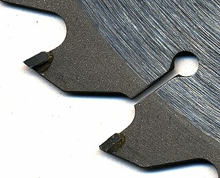
A tipped tool is any cutting tool in which the cutting edge consists of a separate piece of material that is brazed, welded, or clamped onto a body made of another material. In the types in which the cutter portion is an indexable part clamped by a screw, the cutters are called inserts. Tipped tools allow each part of the tool, the shank and the cutter(s), to be made of the material with the best properties for its job. Common materials for the cutters include cemented carbide, polycrystalline diamond, and cubic boron nitride. Tools that are commonly tipped include milling cutters, tool bits, router bits, and saw blades.

<span class="mw-page-title-main">End mill</span> Milling cutter designed to cut axially

An end mill is a type of milling cutter, a cutting tool used in industrial milling applications. It is distinguished from the drill bit in its application, geometry, and manufacture. While a drill bit can only cut in the axial direction, most milling bits can cut in the radial direction. Not all mills can cut axially; those designed to cut axially are known as end mills.

<span class="mw-page-title-main">Boring (manufacturing)</span> Process of enlarging an already-drilled hole with a single-point cutting tool

In machining, boring is the process of enlarging a hole that has already been drilled by means of a single-point cutting tool, such as in boring a gun barrel or an engine cylinder. Boring is used to achieve greater accuracy of the diameter of a hole, and can be used to cut a tapered hole. Boring can be viewed as the internal-diameter counterpart to turning, which cuts external diameters.

In the context of machining, a cutting tool or cutter is typically a hardened metal tool that is used to cut, shape, and remove material from a workpiece by means of machining tools as well as abrasive tools by way of shear deformation. The majority of these tools are designed exclusively for metals.

<span class="mw-page-title-main">Diamond tool</span>

A diamond tool is a cutting tool with diamond grains fixed on the functional parts of the tool via a bonding material or another method. As diamond is a superhard material, diamond tools have many advantages as compared with tools made with common abrasives such as corundum and silicon carbide.

<span class="mw-page-title-main">Cold saw</span> Type of circular saw

A cold saw is a circular saw designed to cut metal which uses a toothed blade to transfer the heat generated by cutting to the chips created by the saw blade, allowing both the blade and material being cut to remain cool. This is in contrast to an abrasive saw, which abrades the metal and generates a great deal of heat absorbed by the material being cut and saw blade.

<span class="mw-page-title-main">Cemented carbide</span> Type of composite material

Cemented carbides are a class of hard materials used extensively for cutting tools, as well as in other industrial applications. It consists of fine particles of carbide cemented into a composite by a binder metal. Cemented carbides commonly use tungsten carbide (WC), titanium carbide (TiC), or tantalum carbide (TaC) as the aggregate. Mentions of "carbide" or "tungsten carbide" in industrial contexts usually refer to these cemented composites.

Arbor milling is a cutting process which removes material via a multi-toothed cutter. An arbor mill is a type of milling machine characterized by its ability to rapidly remove material from a variety of materials. This milling process is not only rapid but also versatile.

<span class="mw-page-title-main">Rake angle</span> Angle between a cutting tool face and the workpiece

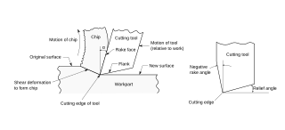
In machining, the rake angle is a parameter used in various cutting processes, describing the angle of the cutting face relative to the workpiece. There are three types of rake angles: positive, zero or neutral, and negative.

<span class="mw-page-title-main">Annular cutter</span> Form of core drill

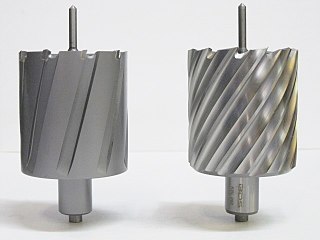
An annular cutter is a form of core drill used to create holes in metal. An annular cutter, named after the annulus shape, cuts only a groove at the periphery of the hole and leaves a solid core or slug at the center.

References

  1. Brown & Sharpe, Automatic Screw Machine Handbook p. 122
  2. Hartness, James (1910), Hartness Flat Turret Lathe Manual, Springfield, Vermont, USA: Jones and Lamson Machine Company, ISBN   9780282208783 , p. 89
  3. Kanigel, Robert (1997), The One Best Way: Frederick Winslow Taylor and the Enigma of Efficiency , Viking Penguin, ISBN   0-670-86402-1