Turret lathe

Last updated
Hartness 3x36 flat turret lathe with cross-sliding head, equipped for bar work, 1910. HartnessTurretLathe.jpg
Hartness 3x36 flat turret lathe with cross-sliding head, equipped for bar work, 1910.

A turret lathe is a form of metalworking lathe that is used for repetitive production of duplicate parts, which by the nature of their cutting process are usually interchangeable. It evolved from earlier lathes with the addition of the turret, which is an indexable toolholder that allows multiple cutting operations to be performed, each with a different cutting tool, in easy, rapid succession, with no need for the operator to perform set-up tasks in between (such as installing or uninstalling tools) or to control the toolpath. The latter is due to the toolpath's being controlled by the machine, either in jig-like fashion, via the mechanical limits placed on it by the turret's slide and stops, or via digitally-directed servomechanisms for computer numerical control lathes.

Contents

The name derives from the way early turrets took the general form of a flattened cylindrical block mounted to the lathe's cross-slide, capable of rotating about the vertical axis and with toolholders projecting out to all sides, and thus vaguely resembled a swiveling gun turret.

Capstan lathe is the usual name in the UK and Commonwealth, though the two terms are also used in contrast: see below, Capstan versus turret.

History

World War II poster. "He Says it should have been over long ago but they're building so dammed many Turret Lathes" - NARA - 534383.jpg
World War II poster.

Turret lathes became indispensable to the production of interchangeable parts and for mass production.

The first turret lathe was built by Stephen Fitch in 1845 to manufacture screws for pistol percussion parts. [2] In the mid-nineteenth century, the need for interchangeable parts for Colt revolvers enhanced the role of turret lathes in achieving this goal as part of the "American system" of manufacturing arms. Clock-making and bicycle manufacturing had similar requirements. [3] Christopher Spencer invented the first fully automated turret lathe in 1873, which led to designs using cam action or hydraulic mechanisms. [2]

From the late-19th through mid-20th centuries, turret lathes, both manual and automatic (i.e., screw machines and chuckers), were one of the most important classes of machine tools for mass production. They were used extensively in the mass production for the war effort in World War II. [4]

Types

There are many variants of the turret lathe. They can be most generally classified by size (small, medium, or large); method of control (manual, automated mechanically, or automated via computer (numerical control (NC) or computer numerical control (CNC)); and bed orientation (horizontal or vertical).

1920 Cincinnati Ames turret lathe. The round turret is on the right. DETAIL OF CIRCA 1920 CINCINNATI AMES MFG. CO. TURRET LATHE SET UP AS FOR PRODUCTION WORK. - Kregel Windmill Company Factory, 1416 Central Avenue, Nebraska City, Otoe County, NE HAER NEB,66-NEBCI,6-25.tif
1920 Cincinnati Ames turret lathe. The round turret is on the right.

Archetypical: horizontal, manual

In the late 1830s a "capstan lathe" with a turret was patented in Britain. [5] The first American turret lathe was invented by Stephen Fitch in 1845. [6] The archetypical turret lathe, and the first in order of historical appearance, is the horizontal-bed, manual turret lathe. The term "turret lathe" without further qualification is still understood to refer to this type. The formative decades for this class of machine were the 1840s through 1860s, when the basic idea of mounting an indexable turret on a bench lathe or engine lathe was born, developed, and disseminated from the originating shops to many other factories. Some important tool-builders in this development were Stephen Fitch; Gay, Silver & Co.; Elisha K. Root of Colt; J.D. Alvord of the Sharps Armory; Frederick W. Howe, Richard S. Lawrence, and Henry D. Stone of Robbins & Lawrence; J.R. Brown of Brown & Sharpe; and Francis A. Pratt of Pratt & Whitney. [7] Various designers at these and other firms later made further refinements.

Semi-automatic

Turret lathe operator machining parts for transport planes, 1942 WomanFactory1940s.jpg
Turret lathe operator machining parts for transport planes, 1942

Sometimes machines similar to those above, but with power feeds and automatic turret-indexing at the end of the return stroke, are called "semi-automatic turret lathes". This nomenclature distinction is blurry and not consistently observed. The term "turret lathe" encompasses them all. During the 1860s, when semi-automatic turret lathes were developed, [6] they were sometimes called "automatic". What we today would call "automatics", that is, fully automatic machines, had not been developed yet. During that era both manual and semi-automatic turret lathes were sometimes called "screw machines", although we today reserve that term for fully automatic machines. [8]

Automatic

During the 1870s through 1890s, the mechanically automated "automatic" turret lathe was developed and disseminated. These machines can execute many part-cutting cycles without human intervention. Thus the duties of the operator, which were already greatly reduced by the manual turret lathe, were even further reduced, and productivity increased. These machines use cams to automate the sliding and indexing of the turret and the opening and closing of the chuck. Thus, they execute the part-cutting cycle somewhat analogously to the way in which an elaborate cuckoo clock performs an automated theater show. Small- to medium-sized automatic turret lathes are usually called "screw machines" or "automatic screw machines", while larger ones are usually called "automatic chucking lathes", "automatic chuckers", or "chuckers".[ citation needed ]

Machine tools of the "automatic" variety, which in the pre-computer era meant mechanically automated, had already reached a highly advanced state by World War I.[ citation needed ]

Computer numerical control

When World War II ended, the digital computer was poised to develop from a colossal laboratory curiosity into a practical technology that could begin to disseminate into business and industry. The advent of computer-based automation in machine tools via numerical control (NC) and then computer numerical control (CNC) displaced to a large extent, but not at all completely, the previously existing manual and mechanically automated machines.

Numerically controlled turrets allow automated selection of tools on a turret. [9] CNC lathes may be horizontal or vertical in orientation and mount six separate tools on one or more turrets. [10] Such machine tools can work in two axes per turret, with up to six axes being feasible for complex work. [10]

Vertical

Vertical turret lathes have the workpiece held vertically, which allows the headstock to sit on the floor and the faceplate to become a horizontal rotating table, analogous to a huge potter's wheel. This is useful for the handling of very large, heavy, short workpieces. Vertical lathes in general are also called "vertical boring mills" or often simply "boring mills"; therefore a vertical turret lathe is a vertical boring mill equipped with a turret. [9]

Other variations

Capstan versus turret

Turret lathe operator, USA, 1942. Beulah Faith, 20, reaming tools for transport on lathe machine1a34938v.jpg
Turret lathe operator, USA, 1942.

The term "capstan lathe" overlaps in sense with the term "turret lathe" to a large extent. In many times and places, it has been understood to be synonymous with "turret lathe". In other times and places it has been held in technical contradistinction to "turret lathe", with the difference being in whether the turret's slide is fixed to the bed (ram-type turret) or slides on the bed's ways (saddle-type turret). [11] [12] The difference in terminology is mostly a matter of United Kingdom and Commonwealth usage versus United States usage. [7]

Flat

A subtype of horizontal turret lathe is the flat-turret lathe. Its turret is flat (and analogous to a rotary table), allowing the turret to pass beneath the part. Patented by James Hartness of Jones & Lamson, and first disseminated in the 1890s, it was developed to provide more rigidity via requiring less overhang in the tool setup, especially when the part is relatively long. [13]

Hollow-hexagon

Hollow-hexagon turret lathes competed with flat-turret lathes by taking the conventional hexagon turret and making it hollow, allowing the part to pass into it during the cut, analogously to how the part would pass over the flat turret. In both cases, the main idea is to increase rigidity by allowing a relatively long part to be turned without the tool overhang that would be needed with a conventional turret, which is not flat or hollow. [14]

Monitor lathe

The term "monitor lathe" formerly (1860s-1940s) referred to the class of small- to medium-sized manual turret lathes used on relatively small work. The name was inspired by the monitor-class warships, which the monitor lathe's turret resembled. Today, lathes of such appearance, such as the Hardinge DSM-59 and its many clones, are still common, but the name "monitor lathe" is no longer current in the industry. [8]

Toolpost turrets and tailstock turrets

Turrets can be added to non-turret lathes (bench lathes, engine lathes, toolroom lathes, etc.) by mounting them on the toolpost, tailstock, or both. Often these turrets are not as large as a turret lathe's, and they usually do not offer the sliding and stopping that a turret lathe's turret does; but they do offer the ability to index through successive tool settings.

Related Research Articles

<span class="mw-page-title-main">Lathe</span> Machine tool which rotates the work piece on its axis

A lathe is a machine tool that rotates a workpiece about an axis of rotation to perform various operations such as cutting, sanding, knurling, drilling, deformation, facing, and turning, with tools that are applied to the workpiece to create an object with symmetry about that axis.

<span class="mw-page-title-main">Machine tool</span> Machine for handling or machining metal or other rigid materials

A machine tool is a machine for handling or machining metal or other rigid materials, usually by cutting, boring, grinding, shearing, or other forms of deformations. Machine tools employ some sort of tool that does the cutting or shaping. All machine tools have some means of constraining the workpiece and provide a guided movement of the parts of the machine. Thus, the relative movement between the workpiece and the cutting tool is controlled or constrained by the machine to at least some extent, rather than being entirely "offhand" or "freehand". It is a power-driven metal cutting machine which assists in managing the needed relative motion between cutting tool and the job that changes the size and shape of the job material.

<span class="mw-page-title-main">Shaper</span> Machine tool which linearly cuts or grinds the workpiece

In machining, a shaper is a type of machine tool that uses linear relative motion between the workpiece and a single-point cutting tool to machine a linear toolpath. Its cut is analogous to that of a lathe, except that it is (archetypally) linear instead of helical.

<span class="mw-page-title-main">Machinist</span> Technician

A machinist is a tradesperson or trained professional who operates machine tools, and has the ability to set up tools such as milling machines, grinders, lathes, and drilling machines.

<span class="mw-page-title-main">Numerical control</span> Computer control of machine tools

In machining, numerical control, also called computer numerical control (CNC), is the automated control of tools by means of a computer. It is used to operate tools such as drills, lathes, mills, grinders, routers and 3D printers. CNC transforms a piece of material into a specified shape by following coded programmed instructions and without a manual operator directly controlling the machining operation.

<span class="mw-page-title-main">Diamond turning</span> Method for making advanced optical elements

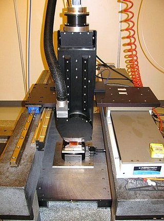
Diamond turning is turning using a cutting tool with a diamond tip. It is a process of mechanical machining of precision elements using lathes or derivative machine tools equipped with natural or synthetic diamond-tipped tool bits. The term single-point diamond turning (SPDT) is sometimes applied, although as with other lathe work, the "single-point" label is sometimes only nominal. The process of diamond turning is widely used to manufacture high-quality aspheric optical elements from crystals, metals, acrylic, and other materials. Plastic optics are frequently molded using diamond turned mold inserts. Optical elements produced by the means of diamond turning are used in optical assemblies in telescopes, video projectors, missile guidance systems, lasers, scientific research instruments, and numerous other systems and devices. Most SPDT today is done with computer numerical control (CNC) machine tools. Diamonds also serve in other machining processes, such as milling, grinding, and honing. Diamond turned surfaces have a high specular brightness and require no additional polishing or buffing, unlike other conventionally machined surfaces.

<span class="mw-page-title-main">Tool and cutter grinder</span>

A Tool and Cutter Grinder is used to sharpen milling cutters and tool bits along with a host of other cutting tools.

<span class="mw-page-title-main">Turning</span> Machining process

Turning is a machining process in which a cutting tool, typically a non-rotary tool bit, describes a helix toolpath by moving more or less linearly while the workpiece rotates.

<span class="mw-page-title-main">Metal lathe</span> Machine tool used to remove material from a rotating workpiece

In machining, a metal lathe or metalworking lathe is a large class of lathes designed for precisely machining relatively hard materials. They were originally designed to machine metals; however, with the advent of plastics and other materials, and with their inherent versatility, they are used in a wide range of applications, and a broad range of materials. In machining jargon, where the larger context is already understood, they are usually simply called lathes, or else referred to by more-specific subtype names. These rigid machine tools remove material from a rotating workpiece via the movements of various cutting tools, such as tool bits and drill bits.

A screw machine may refer to a:

<span class="mw-page-title-main">Die head</span>

A die head is a threading die that is used in the high volume production of threaded fasteners.

<span class="mw-page-title-main">James Hartness</span> American engineer and Vermont politician (1861–1934)

James Hartness was an American business executive, inventor, mechanical engineer, entrepreneur, amateur astronomer, and politician who served as the 58th governor of Vermont from 1921 to 1923.

In manufacturing, threading is the process of creating a screw thread. More screw threads are produced each year than any other machine element. There are many methods of generating threads, including subtractive methods ; deformative or transformative methods ; additive methods ; or combinations thereof.

<span class="mw-page-title-main">CNC router</span> Computer-controlled cutting machine

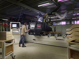
A computer numerical control (CNC) router is a computer-controlled cutting machine which typically mounts a hand-held router as a spindle which is used for cutting various materials, such as wood, composites, metals, plastics, glass, and foams. CNC routers can perform the tasks of many carpentry shop machines such as the panel saw, the spindle moulder, and the boring machine. They can also cut joinery such as mortises and tenons.

<span class="mw-page-title-main">Multiaxis machining</span> Manufacturing processes using tools that can move in 4 or more directions

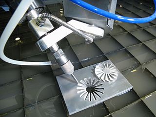
Multiaxis machining is a manufacturing process that involves tools that move in 4 or more directions and are used to manufacture parts out of metal or other materials by milling away excess material, by water jet cutting or by laser cutting. This type of machining was originally performed mechanically on large complex machines. These machines operated on 4, 5, 6, and even 12 axes which were controlled individually via levers that rested on cam plates. The cam plates offered the ability to control the tooling device, the table in which the part is secured, as well as rotating the tooling or part within the machine. Due to the machines size and complexity it took extensive amounts of time to set them up for production. Once computer numerically controlled machining was introduced it provided a faster, more efficient method for machining complex parts.

<span class="mw-page-title-main">Fay automatic lathe</span> Machine tool

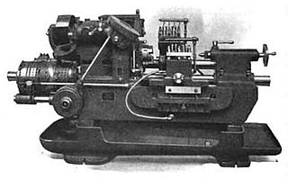
The Fay automatic lathe was an automatic lathe tailored to cutting workpieces that were mounted on centers. It could also do chucking work. Examples of workpieces included automotive steering knuckles and transmission gears, and such work done on mandrels as flanges, disks, and hubs. The machine tool was developed by F.C. Fay of Philadelphia and improved by Otto A. Schaum. It was originally manufactured by the Fay & Scott Machine Shop. James Hartness acquired manufacturing rights on behalf of the Jones & Lamson Machine Company and manufactured an improved version, developed under the management of Ralph Flanders.

<span class="mw-page-title-main">Automatic lathe</span>

In metalworking and woodworking, an automatic lathe is a lathe with an automatically controlled cutting process. Automatic lathes were first developed in the 1870s and were mechanically controlled. From the advent of NC and CNC in the 1950s, the term automatic lathe has generally been used for only mechanically controlled lathes, although some manufacturers market Swiss-type CNC lathes as 'automatic'.

<span class="mw-page-title-main">Milling (machining)</span> Removal of material from a workpiece using rotating tools

Milling is the process of machining using rotary cutters to remove material by advancing a cutter into a workpiece. This may be done by varying directions on one or several axes, cutter head speed, and pressure. Milling covers a wide variety of different operations and machines, on scales from small individual parts to large, heavy-duty gang milling operations. It is one of the most commonly used processes for machining custom parts to precise tolerances.

The history of numerical control (NC) began when the automation of machine tools first incorporated concepts of abstractly programmable logic, and it continues today with the ongoing evolution of computer numerical control (CNC) technology.

In machining, an automatic tool changer (ATC) is used in computerized numerical control (CNC) machine tools to improve the production and tool carrying capacity of the machine. ATCs change tools rapidly, reducing non-productive time. They are generally used to improve the capacity of the machines to work with a number of tools. They are also used to change worn out or broken tools. They are one more step towards complete automation.

References

  1. Hartness 1910.
  2. 1 2 Zhang, Ce; Yang, Jianming (2020-01-03). A History of Mechanical Engineering. Springer Nature. pp. 128, 177–9, 429. ISBN   978-981-15-0833-2.
  3. Hounshell, David (1985). From the American System to Mass Production, 1800-1932: The Development of Manufacturing Technology in the United States. JHU Press. pp. 48–50. ISBN   978-0-8018-3158-4.
  4. Parker, Dana T. Building Victory: Aircraft Manufacturing in the Los Angeles Area in World War II, p. 81, 123, Cypress, CA, 2013. ISBN   978-0-9897906-0-4.
  5. Editors (1924). American Machinist. McGraw-Hill. p. 273.{{cite book}}: |last= has generic name (help)
  6. 1 2 Crosher, William P. (2014). A Gear Chronology. Bloomington, Indiana: Xlibris. p. 144. ISBN   978-1499071146.
  7. 1 2 Rolt 1965 , p. 165.
  8. 1 2 Editors (1901). "Part 5: Lathe Work". Reading working drawings. Arithmetic. Measuring instruments. Lathe work. Colliery Engineer Company. pp. 3–11.{{cite book}}: |last= has generic name (help)
  9. 1 2 Bawa, H. S. (2004). Manufacturing processes. Vol. 1. New Delhi: Tata McGraw-Hill. p. 57. ISBN   0-07-053525-6. OCLC   57660758.
  10. 1 2 Smid, Peter (2003). CNC programming handbook : a comprehensive guide to practical CNC programming (2nd ed.). New York: Industrial Press. pp.  11–14. ISBN   0-8311-3158-6. OCLC   52364066.
  11. Capstan and Turret differences
  12. H.W. Ward & Co., Ltd 1938.
  13. Roe 1937 , pp. 34–36.
  14. Editors (1921). A.S.M.E. Mechanical Catalog and Directory. American Society of Mechanical Engineers. p. 456.{{cite book}}: |last= has generic name (help)

Bibliography