Tap in a wrench for creating female threads (left), and die in a wrench for creating male threads (right).
In the context of threading, taps and dies are two classes of tools used to create or repair screw threads. A tap is used to cut or form the female portion of the mating pair (e.g. a nut). A die is a cutting tool used to cut the male portion of the mating pair (e.g. a bolt). The process of cutting or forming threads using a tap is called tapping, whereas the process using a die is called threading.
Both tools can also be used to clean up or repair a thread, which is called chasing. However, using an ordinary tap or die to clean threads generally removes some material, which results in looser, weaker threads. Because of this, machinists generally clean threads with special taps and dies—called chasers—made for that purpose. Chasers are made of softer materials and don't cut new threads. However they still fit tighter than actual fasteners, and are fluted like regular taps and dies so debris can escape. Car mechanics, for example, use chasers on spark plug threads, to remove corrosion and carbon build-up.
Taps and dies are available in many hardware stores, home improvement centers and automotive part retailers in common sizes and pipe (Home improvement) sizes. Online industrial suppliers have an immense selection of various taps and dies.[1] Manufacturers and DIY websites have instructions on how to use the tools.[2][3]
History
While modern nuts and bolts are routinely made of metal, this was not the case in earlier ages, when woodworking tools were employed to fashion very large wooden bolts and nuts for use in winches, windmills, watermills, and flour mills of the Middle Ages; the ease of cutting and replacing wooden parts was balanced by the need to resist large amounts of torque, and bear up against ever heavier loads of weight. As the loads grew even heavier, bigger and stronger bolts were needed to resist breakage. Some nuts and bolts were measured by the foot or yard. This development eventually led to a complete replacement of wood parts with metal parts of an identical measure. When a wooden part broke, it usually snapped, ripped, or tore. With the splinters having been sanded off, the remaining parts were reassembled, encased in a makeshift mold of clay, and molten metal poured into the mold, so that an identical replacement could be made on the spot.
Die and tap from Löffelholz-Codex (Nuremberg 1505)
Opened die from Löffelholz-Codex (Nuremberg 1505)
Metalworking taps and dies were often made by their users during the 16th and 17th centuries (especially if the user was skilled in tool making), using such tools as lathes and files for the shaping, and the smithy for hardening and tempering. Thus builders of, for example, locomotives, firearms, or textile machinery were likely to make their own taps and dies. During the 19th century the machining industries evolved greatly, and the practice of buying taps and dies from suppliers specializing in them gradually supplanted most such in-house work. Joseph Clement was one such early vendor of taps and dies, starting in 1828.[4] With the introduction of more advanced milling practice in the 1860s and 1870s, tasks such as cutting a tap's flutes with a hand file became a thing of the past. In the early 20th century, thread-grinding practice went through significant evolution, further advancing the state of the art (and applied science) of cutting screw threads, including those of taps and dies.
The largest tap and die company to exist in the United States was Greenfield Tap & Die (GTD) of Greenfield, Massachusetts. GTD was so vital to the Allied war effort from 1940–1945 that anti-aircraft guns were placed around its campus in anticipation of possible Axis air attack[5]. The GTD brand is now a part of Widia Products Group.
Tap
From top: Bottoming, plug and taper taps (US usage), or plug, second and taper (UK usage).Various taps.A tap and "T" wrenchVarious tap handles (wrenches).
A tap cuts or forms a thread on the inside surface of a hole, creating a female surface that functions like a nut. The three taps in the image illustrate the basic types commonly used by most machinists:
Bottoming tap
The tap illustrated in the top of the image has a continuous cutting edge with almost no taper — between 1 and 1.5 threads of taper is typical.[6][7] This feature enables a bottoming tap to cut threads to the bottom of a blind hole. A bottoming tap is usually used to cut threads in a hole that has already been partially threaded using one of the more tapered types of tap; the tapered end ("tap chamfer") of a bottoming tap is too short to successfully start into an unthreaded hole. In the US, they are commonly known as bottoming taps, but in Australia and Britain they are also known as plug taps.
The tap illustrated in the middle of the image has tapered cutting edges, which assist in aligning and starting the tap into an untapped hole. The number of tapered threads typically ranges from 3 to 5.[6] Plug taps are the most commonly used type of tap.[citation needed] In the US, they are commonly known as plug taps, whereas in Australia and Britain they are commonly known as second taps.
Taper tap
The small tap illustrated at the bottom of the image is similar to an intermediate tap but has a more pronounced taper to the cutting edges. This feature gives the taper tap a very gradual cutting action that is less aggressive than that of the plug tap. The number of tapered threads typically ranges from 8 to 10.[6] A taper tap is most often used when the material is difficult to work (e.g., alloy steel) or the tap is of a very small diameter and thus prone to breakage.
Power taps
The above taps are generally referred to as hand taps, since they are manually operated. During operation, the machinist must periodically reverse a hand tap to break the chip (also known as swarf) that forms from cutting. This prevents the cut material from crowding and breaking the tap.
The most common type of power driven tap is the "spiral point" plug tap, also referred to as a "gun" tap, whose cutting edges are angularly displaced relative to the tap centerline.A spiral point plug tap ("gun" tap). This feature causes the tap to continuously break the chip and eject it forward into the hole, preventing crowding. Spiral point taps are usually used in holes that go all the way through the material, so that the chips can escape. Another version of the spiral point plug tap is the spiral flute tap, whose flutes resemble those of a twist drill. Spiral flute taps are widely used in high speed, automatic tapping operations due to their ability to work well in blind holes.
Forming tap
A forming tap, aka fluteless tap, cold forming or roll tap, functions quite differently than a cut tap, in that it forcefully displaces the metal into a thread shape upon being turned into the hole, instead of cutting metal from the sides of the hole as cutting taps do.Photograph of a 3/4"-10 Form (Cold) tap A forming tap has lobes periodically spaced around the tap which actually do the thread forming as the tap is advanced into a properly sized hole, and the threads behind the lobes are slightly recessed to reduce contact friction. Since there is no need to provide space for evacuating chips, these recesses are much more subtle than a cutting tap's flutes and the tap appears very nearly just like a plain thread. Since the tap does not produce chips, there is no need to periodically back out the tap to clear away chips, which can jam and break a cutting tap if allowed to accumulate. The problem of accumulated chips is particularly acute in blind holes, so thread forming is particularly suited to such applications. Forming taps only work in malleable materials such as mild steel or aluminum. Formed threads are typically stronger than cut threads. Note that the tap drill size is larger than that used for a cutting tap as shown in most tap drill tables, and an accurate hole size is required; a slightly undersized hole can break the tap. Proper lubrication is essential because of the frictional forces involved, therefore a lubricating oil is used instead of cutting oil.Form (Left) and Cut (Right) 5/8-18 taps showing cross sections Form taps are much stronger than cut taps, as can be seen by cross sections of the same size tap. This significantly lessens tap breakage (Tap breakage discussed below under Machine Tapping)[8]
Holes
Whether manual or automatic, the processing of tapping begins with forming (usually by drilling) and slightly countersinking a hole to a diameter somewhat smaller than the tap's major diameter. The correct hole diameter is listed on a drill and tap size chart, a standard reference in many machine shops. The proper diameter for the drill is called the tap drill size. Without a tap drill chart, you can compute the correct tap drill diameter with:
where is the tap drill size, is the major diameter of the tap (e.g., 3⁄8 in for a 3⁄8-16 tap), and is the thread pitch (1⁄16inch in the case of a 3⁄8-16 tap). For a 3⁄8-16 tap, the above formula would produce 5⁄16, which is the correct tap drill diameter. The above formula ultimately results in an approximate 75% thread.
Since metric threads specify the pitch directly, the correct tap drill diameter for metric-sized taps is computed with:
where is the tap drill size, is the major diameter of the tap (e.g., 10mm for a M10×1.5 tap), and pitch is the pitch of the thread (1.5mm in the case of a standard M10 tap) and so the correct drill size is 8.5mm. This works for both fine and coarse pitches, and also produces an approximate 75% thread.
Tap sequence
With soft or average hardness materials, such as plastic, aluminum or mild steel, common practice is to use an intermediate (plug) tap to cut the threads. If the threads must extend to the bottom of a blind hole, the machinist uses an intermediate (plug) tap to cut threads until the point of the tap reaches bottom, and then switches to a bottoming tap to finish. The machinist must frequently eject chips to avoid jamming or breaking the tap. With hard materials, the machinist may start with a taper tap, whose less severe diameter transition reduces the torque required to cut threads. To threads to the bottom of a blind hole, the machinist follows the taper tap with an intermediate (plug) tap, and then a bottoming tap to finish.
Machine tapping
Tapping may either be achieved by a hand tapping by using a set of taps (first tap, second tap & final (finish) tap) or using a machine to do the tapping, such as a lathe, radial drilling machine, bench type drill machine, pillar type drill machine, vertical milling machines, HMCs, VMCs. Machine tapping is faster, and generally more accurate because human error is eliminated. Final tapping is achieved with single tap.
Although in general machine tapping is more accurate, tapping operations have traditionally been very tricky to execute due to frequent tap breakage and inconsistent quality of tapping.
Common reasons for tap breakage are:
Tap-related problems:
Wearing of tap cannot be easily quantified (use of worn-out taps)
Use of tap with improper tap geometry for a particular application.
Over- or under-feeding the tap, causing breakage in tension or compression.
Use of improper and/or insufficient cutting lubricant.
Absence of a torque limiting feature.
Improper or zero float for use with screw machines (recommended feed .1 slower to establish float for 40tpi or higher and .15 slower for 40tpi or finer[9])
Improper spindle speed.
To overcome these problems, special tool holders are required to minimize the chances of tap breakage during tapping. These are usually classified as conventional tool holders and CNC tool holders.
Tool holders for tapping operations
Various tool holders may be used for tapping depending on the requirements of the user:
Aids for hand-tapping (simple jigs and fixtures)
The biggest problem with simple hand-tapping is accurately aligning the tap with the hole so that they are coaxial—in other words, going in straight instead of on an angle. The operator must get this alignment close to ideal to produce good threads and not break the tap. The deeper the thread depth, the more pronounced the effect of the angular error. With a depth of 1 or 2 diameters, it matters little. With depths beyond 2 diameters, the error becomes too pronounced to ignore. Another fact about alignment is that the first thread cut or two establishes the direction that the rest of the threads will follow. You can't correct the angle after the first thread or two.
To help with this alignment task, several kinds of jigs and fixtures can be used to provide the correct geometry (i.e., accurate coaxiality with the hole) without having to use freehand skill to approximate it:
Hand-tapper: A simple fixture analogous to an arbor press in its basic shape. Its spindle is thus held accurately perpendicular to the work. Standard taps are held in the spindle, and the operator turns the spindle manually via a handlebar. This fixture obviates the need for the operator to carefully and skillfully approximate perpendicularity, which even for a skilled operator can easily result in a 2–5° error.
Tapping guide, or "tap and reamer aligner/holder", a simple conical guide slipped over a tap when using a regular tap handle. As with a hand-tapper, the basic principle is simply that of a jig or fixture to provide the correct alignment.
Heads for machine tool spindles
Tapping attachments: these may be normal (available in a range of tap sizes) or quick-change
Quick-change drilling and tapping chucks (variations available for both CNC and manual-control tools)
Rigid tapping attachments (for CNC)
Generally the following features are required of tapping holders:
Twin chucking: tap is held at points of both its circular and square cross-section. Gripping the circular section assures concentricity to the machine spindle, and gripping the square produces positive rotational drive.
Safety clutch: The built in safety mechanism operates as soon as the set torque limit is attained to save the tap from breakage.
Float radial parallel: small misalignments are taken care of by this float.
Length compensation: built in length compensation takes care of small push or pull to the spindle or feed difference.
Tapping case studies with typical examples of tapping operations in various environments are shown on source machinetoolaid.com
Tapping stations
Tapping stations are worktables with a tapping head attached to the end of a pantograph-style arm similar to that of a balanced-arm lamp. The operator guides the tapping head to each (already-drilled) hole and quickly taps it.
Drilling and tapping centers, whose name sounds similar to that of tapping stations, are actually light-duty, affordable machining centers of 2, 2.5, or 3 axes that are designed for a life of mainly drilling and tapping with limited milling use.
Double-lead taps and insert taps need different speeds and feeds, and different starting hole diameters than other taps.
A comprehensive reference for US tap and drill bit sizes can be found in the chart provided by Albany County Fasteners. This chart includes detailed specifications for machine screw size, threads per inch, major and minor diameters, and appropriate drill sizes for different materials.
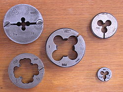
A die cuts an external thread on cylindrical material, such as a rod, which creates a male threaded piece that functions like a bolt. Dies are generally made in two styles: solid and adjustable. An adjustable die may be adjusted either by an integrated screw or by a set of screws set in to the die holder (termed a "die stock"). Integral adjusting screws may be arranged to work axially, where the movement of the adjusting screw into a threaded hole in the die forces the slit section of the die open, or tangentially where a screw threaded in to one side of the slit bears against the opposite side of the slit. Dies without integrated screws are adjusted inside the die stock by radially arranged screws. Two screws in the stock bear in to indentations on either side of the slit, tending to squeeze the slit closed, whilst a third screw with a tapered tip screws in to the slit forcing it open. Working these three screws against each other adjusts the die.
Integrated screws appear to be common in the US but are almost unknown in the UK and Europe.
The dies shown in the image to the right are adjustable:
top left: an older split die, with top adjusting screw
bottom left: a one piece die with top adjusting screw
center: a one piece die with side adjusting screw (barely visible on the full image)
right: two dies without integrated adjusting screws
Solid dies cut a nominal thread form and depth, whose accuracy is subject to the precision the die was made with, and the effects of wear. Adjustable dies can be slightly compressed or expanded to provide some compensation for wear, or to achieve different classes of thread fit (class A, B and more rarely, C). Adjustable taps also exist but are not common. These have a tip that is split through the flutes and an axial screw which forces the cutting edges slightly apart.
The work piece (blank) to be threaded, which is usually slightly smaller in diameter than the die's major diameter, is given a slight taper (chamfer) at the end that is to be threaded. This chamfer helps center the die on the blank and reduces the force required to start the thread cutting.[13] Once the die has started, it self-feeds. Periodic reversal of the die is often required to break the chip and prevent crowding.
Die (left) and Chaser (right) aka Die Nut, Rethreading Die with Wrench Shown for Prospective
Rethreading Die
Rethreading dies, also known as Die nuts, are dies made for cleaning up damaged threads, which is referred to as "chasing."[14] These dies have no split for resizing, minimal "gullet" and are made from a hexagonal bar sized so that the wrench used for a standard nut of that size may be used to turn them. Rethreading dies cannot be used to cut new threads as they lack chip forming teeth. Note, however the external profile of a die does not strictly map to its function. Manufacturers of dies have produced models in a hex form which are intended for the creation of new threads.[15] These appear identical to solid dies in all aspects besides the external shape. Hexagonal thread cutting dies are used with a die stock with hexagonal holding features.
The use of a suitable lubricant is essential with most tapping and threading operations. Recommended lubricants for some common materials are as follows:
Petroleum-based cutting oil mixed with a small amount (approximately 10 percent) of kerosene or mineral spirits. This mixture is also suitable for use with stainless steel.
Kerosene or mineral spirits mixed with a small amount (15–25 percent) of petroleum-based cutting oil. In some cases, products such as WD-40, CRC 5-56 and 3-In-One Oil are acceptable substitutes.
This page is based on this Wikipedia article Text is available under the CC BY-SA 4.0 license; additional terms may apply. Images, videos and audio are available under their respective licenses.