Indexing head

Last updated
Indexing head and tailstock set up on a milling machine's table. IndexingHead-Tailstock.jpg
Indexing head and tailstock set up on a milling machine's table.

An indexing head, also known as a dividing head or spiral head, [1] is a specialized tool that allows a workpiece to be circularly indexed; that is, easily and precisely rotated to preset angles or circular divisions. Indexing heads are usually used on the tables of milling machines, but may be used on many other machine tools including drill presses, grinders, and boring machines. Common jobs for a dividing head include machining the flutes of a milling cutter, cutting the teeth of a gear, milling curved slots, or drilling a bolt hole circle around the circumference of a part. [2]

Contents

The tool is similar to a rotary table except that it is designed to be tilted as well as rotated and often allows positive locking at finer gradations of rotation, including through differential indexing. Most adjustable designs allow the head to be tilted from 10° below horizontal to 90° vertical, at which point the head is parallel with the machine table.

The workpiece is held in the indexing head in the same manner as a metalworking lathe. This is most commonly a chuck but can include a collet fitted directly into the spindle on the indexing head, faceplate, or between centers. If the part is long then it may be supported with the help of an accompanying tailstock.

Manual indexing heads

Cross-section of an indexing head Indexing head cross-section.png
Cross-section of an indexing head
Interchangeable indexing plates IndexingPlatesStyle1.jpg
Interchangeable indexing plates
A dividing head mounted on the table of a small milling machine. The direct indexing plate and center are visible facing the camera. An interchangeable indexing plate is visible on the left side. IndexingHead-SimplePlate.jpg
A dividing head mounted on the table of a small milling machine. The direct indexing plate and center are visible facing the camera. An interchangeable indexing plate is visible on the left side.

Indexing is an operation of dividing a periphery of a cylindrical workpiece into equal number of divisions by the help of index crank and index plate. A manual indexing head includes a hand crank. Rotating the hand crank in turn rotates the spindle and therefore the workpiece. The hand crank uses a worm gear drive to provide precise control of the rotation of the work. The work may be rotated and then locked into place before the cutter is applied, or it may be rotated during cutting depending on the type of machining being done.

Most dividing heads operate at a 40:1 ratio; that is 40 turns of the hand crank generates 1 revolution of the spindle or workpiece. In other words, 1 turn of the hand crank rotates the spindle by 9 degrees. Because the operator of the machine may want to rotate the part to an arbitrary angle indexing plates are used to ensure the part is accurately positioned.

Direct indexing plate: Most dividing heads have an indexing plate permanently attached to the spindle. This plate is located at the end of the spindle, very close to where the work would be mounted. It is fixed to the spindle and rotates with it. This plate is usually equipped with a series of holes that enables rapid indexing to common angles, such as 30, 45, or 90 degrees. A pin in the base of the dividing head can be extended into the direct indexing plate to lock the head quickly into one of these angles. [3] The advantage of the direct indexing plate is that it is fast and simple, and no calculations are required to use it. The disadvantage is that it can only be used for a limited number of angles.

Interchangeable indexing plates are used when the work must be rotated to an angle not available on the direct indexing plate. Because the hand crank is fixed to the spindle at a known ratio (commonly 40:1) the dividing plates mounted at the handwheel can be used to create finer divisions for precise orientation at irregular angles. These dividing plates are provided in sets of several plates. Each plate has rings of holes with different divisions. For example, an indexing plate might have three rows of holes with 24, 30, and 36 holes in each row. A pin on the hand crank engages these holes. Index plates with up to 400 holes are available. [2] Only one such plate can be mounted to the dividing head at a time. The plate is selected by the machinist based on exactly what angle he wishes to index to.

For example, if a machinist wanted to index (rotate) his workpiece by 22.5 degrees, then he would turn the hand crank two full revolutions plus one-half of a turn. Since each full revolution is 9 degrees and a half-revolution is 4.5 degrees, the total is 22.5 (9 + 9 + 4.5 = 22.5). The one-half turn can easily be done precisely using any indexing plate with an even number of holes and rotating to the halfway point (Hole #8 on the 16-hole ring).

Brown and Sharpe indexing heads include a set of 3 indexing plates. The plates are marked #1, #2 and #3, or "A", "B" and "C". Each plate contains 6 rows of holes. Plate #1 or "A" has 15, 16, 17, 18, 19, and 20 holes. Plate #2 or "B" has 21, 23, 27, 29, 31, and 33 holes. Plate #3 or "C" has 37, 39, 41, 43, 47, and 49 holes.[ citation needed ]

Universal Dividing heads: some manual indexing heads are equipped with a power drive provision. This allows the rotation of the dividing head to be connected to the table feed of the milling machine instead of using a hand crank. A set of change gears is provided to select the ratio between the table feed and rotation. This setup allows the machining of spiral or helical features such as spiral gears, worms, or screw type parts because the part is simultaneously rotated at the same time it is moved in the horizontal direction. This setup is called a "PTO dividing head".

CNC indexing heads

CNC indexing heads are similar in design to the manual variety, except that they have a servo motor coupled to the spindle instead of a hand crank and indexing plates. The servo motor is electronically controlled to index the work to the required position. The control can either be a simple keypad for the operator, or it may be fully CNC controlled.

CNC indexing heads may be controlled in two different modes. The most basic method of operation uses simple control functions built into the dividing head. It does not require a CNC machine. The operator enters the desired angle into a control box attached to the indexing head, and it automatically rotates to the desired position and locks into place for machining. Changing angles is as simple as typing a new angle value onto the control pad. This is simpler than setting up a manual indexing head because there is no need to interchange indexing plates or to calculate which hole positions to use. It is also faster for repetitive operations because the work can be indexed by simply pressing a button, eliminating the need to count rotations of the hand crank or specific hole positions on the indexing plate. A CNC dividing head may be used in this manner on either manual or CNC machinery.

Most CNC dividing heads are also able to function as a full CNC axis and may be wired into the control of a CNC machine. This enables the machine's main CNC controller to control the indexing head just like it would control the other axes of the machine. This can be used to machine complex 3D shapes, helices with a non-constant pitch, and similar exotic parts. This mode of operation cannot be used on a manual machine tool because it requires a full CNC controller to operate.

Related Research Articles

<span class="mw-page-title-main">Router (woodworking)</span> Woodworking power tool

The router is a power tool with a flat base and a rotating blade extending past the base. The spindle may be driven by an electric motor or by a pneumatic motor. It routs an area in hard material, such as wood or plastic. Routers are used most often in woodworking, especially cabinetry. They may be handheld or affixed to router tables. Some woodworkers consider the router one of the most versatile power tools.

<span class="mw-page-title-main">Lathe</span> Machine tool which rotates the work piece on its axis

A lathe is a machine tool that rotates a workpiece about an axis of rotation to perform various operations such as cutting, sanding, knurling, drilling, deformation, facing, and turning, with tools that are applied to the workpiece to create an object with symmetry about that axis.

<span class="mw-page-title-main">Drill</span> Tool used to create holes

A drill is a tool used for making round holes or driving fasteners. It is fitted with a bit, either a drill or driver chuck. Hand-operated types are dramatically decreasing in popularity and cordless battery-powered ones proliferating due to increased efficiency and ease of use.

<span class="mw-page-title-main">Shaper</span> Machine tool which linearly cuts or grinds the workpiece

In machining, a shaper is a type of machine tool that uses linear relative motion between the workpiece and a single-point cutting tool to machine a linear toolpath. Its cut is analogous to that of a lathe, except that it is (archetypally) linear instead of helical.

<span class="mw-page-title-main">Metalworking</span> Process of making items from metal

Metalworking is the process of shaping and reshaping metals to create useful objects, parts, assemblies, and large scale structures. As a term it covers a wide and diverse range of processes, skills, and tools for producing objects on every scale: from huge ships, buildings, and bridges down to precise engine parts and delicate jewelry.

<span class="mw-page-title-main">Drilling</span> Cutting process that uses a drill bit to cut a circular hole into the workpiece

Drilling is a cutting process where a drill bit is spun to cut a hole of circular cross-section in solid materials. The drill bit is usually a rotary cutting tool, often multi-point. The bit is pressed against the work-piece and rotated at rates from hundreds to thousands of revolutions per minute. This forces the cutting edge against the work-piece, cutting off chips (swarf) from the hole as it is drilled.

<span class="mw-page-title-main">Grinding machine</span> Machine tool used for grinding

A grinding machine, often shortened to grinder, is a power tool used for grinding. It is a type of machining using an abrasive wheel as the cutting tool. Each grain of abrasive on the wheel's surface cuts a small chip from the workpiece via shear deformation.

<span class="mw-page-title-main">Plasma cutting</span> Process

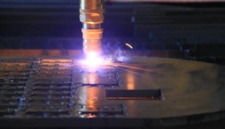
Plasma cutting is a process that cuts through electrically conductive materials by means of an accelerated jet of hot plasma. Typical materials cut with a plasma torch include steel, stainless steel, aluminum, brass and copper, although other conductive metals may be cut as well. Plasma cutting is often used in fabrication shops, automotive repair and restoration, industrial construction, and salvage and scrapping operations. Due to the high speed and precision cuts combined with low cost, plasma cutting sees widespread use from large-scale industrial computer numerical control (CNC) applications down to small hobbyist shops.

<span class="mw-page-title-main">Chuck (engineering)</span> Clamp used to hold an object with radial symmetry, especially a cylinder

A chuck is a specialized type of clamp used to hold an object with radial symmetry, especially a cylinder. In a drill, a mill and a transmission, a chuck holds the rotating tool; in a lathe, it holds the rotating workpiece.

<span class="mw-page-title-main">Punch press</span>

A punch press is a type of machine press used to cut holes in material. It can be small and manually operated and hold one simple die set, or be very large, CNC operated, with a multi-station turret and hold a much larger and complex die set.

<span class="mw-page-title-main">Turning</span> Machining process

Turning is a machining process in which a cutting tool, typically a non-rotary tool bit, describes a helix toolpath by moving more or less linearly while the workpiece rotates.

<span class="mw-page-title-main">Lathe center</span>

A lathe center, often shortened to center, is a tool that has been ground to a point to accurately position a workpiece on an axis. They usually have an included angle of 60°, but in heavy machining situations an angle of 75° is used.

<span class="mw-page-title-main">Metal lathe</span> Machine tool used to remove material from a rotating workpiece

In machining, a metal lathe or metalworking lathe is a large class of lathes designed for precisely machining relatively hard materials. They were originally designed to machine metals; however, with the advent of plastics and other materials, and with their inherent versatility, they are used in a wide range of applications, and a broad range of materials. In machining jargon, where the larger context is already understood, they are usually simply called lathes, or else referred to by more-specific subtype names. These rigid machine tools remove material from a rotating workpiece via the movements of various cutting tools, such as tool bits and drill bits.

<span class="mw-page-title-main">Rotary table</span>

A rotary table is a precision work positioning device used in metalworking. It enables the operator to drill or cut work at exact intervals around a fixed axis. Some rotary tables allow the use of index plates for indexing operations, and some can also be fitted with dividing plates that enable regular work positioning at divisions for which indexing plates are not available. A rotary fixture used in this fashion is more appropriately called a dividing head.

<span class="mw-page-title-main">Boring (manufacturing)</span> Process of enlarging an already-drilled hole with a single-point cutting tool

In machining, boring is the process of enlarging a hole that has already been drilled by means of a single-point cutting tool, such as in boring a gun barrel or an engine cylinder. Boring is used to achieve greater accuracy of the diameter of a hole, and can be used to cut a tapered hole. Boring can be viewed as the internal-diameter counterpart to turning, which cuts external diameters.

Indexing in reference to motion is moving into a new position or location quickly and easily but also precisely. When indexing a machine part, its new location is known to within a few hundredths of a millimeter, or often even to within a few thousandths of a millimeter, despite the fact that no elaborate measuring or layout was needed to establish that location. In reference to multi-edge cutting inserts, indexing is the process of exposing a new cutting edge for use. Indexing is a necessary kind of motion in many areas of mechanical engineering and machining. An object that indexes, or can be indexed, is said to be indexable.

In manufacturing, threading is the process of creating a screw thread. More screw threads are produced each year than any other machine element. There are many methods of generating threads, including subtractive methods ; deformative or transformative methods ; additive methods ; or combinations thereof.

<span class="mw-page-title-main">Multiaxis machining</span> Manufacturing processes using tools that can move in 4 or more directions

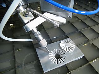
Multiaxis machining is a manufacturing process that involves tools that move in 4 or more directions and are used to manufacture parts out of metal or other materials by milling away excess material, by water jet cutting or by laser cutting. This type of machining was originally performed mechanically on large complex machines. These machines operated on 4, 5, 6, and even 12 axes which were controlled individually via levers that rested on cam plates. The cam plates offered the ability to control the tooling device, the table in which the part is secured, as well as rotating the tooling or part within the machine. Due to the machines size and complexity it took extensive amounts of time to set them up for production. Once computer numerically controlled machining was introduced it provided a faster, more efficient method for machining complex parts.

<span class="mw-page-title-main">Automatic lathe</span>

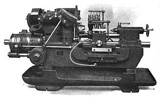
In metalworking and woodworking, an automatic lathe is a lathe with an automatically controlled cutting process. Automatic lathes were first developed in the 1870s and were mechanically controlled. From the advent of NC and CNC in the 1950s, the term automatic lathe has generally been used for only mechanically controlled lathes, although some manufacturers market Swiss-type CNC lathes as 'automatic'.

<span class="mw-page-title-main">Milling (machining)</span> Removal of material from a workpiece using rotating tools

Milling is the process of machining using rotary cutters to remove material by advancing a cutter into a workpiece. This may be done by varying directions on one or several axes, cutter head speed, and pressure. Milling covers a wide variety of different operations and machines, on scales from small individual parts to large, heavy-duty gang milling operations. It is one of the most commonly used processes for machining custom parts to precise tolerances.

References

  1. Burghardt 1922 , p. 244.
  2. 1 2 Barnwell, George W. (1941), The new encyclopedia of machine shop practice, PARTH.BAROT & Co., pp. 234–235.
  3. Burghardt 1922 , p. 245.

Bibliography