A reamer is a type of rotary cutting tool used in metalworking. Precision reamers are designed to enlarge the size of a previously formed hole by a small amount but with a high degree of accuracy to leave smooth sides. There are also non-precision reamers which are used for more basic enlargement of holes or for removing burrs. The process of enlarging the hole is called reaming. There are many different types of reamer and they may be designed for use as a hand tool or in a machine tool, such as a milling machine or drill press.
A typical reamer consists of a set of parallel straight or helical cutting edges along the length of a cylindrical body. Each cutting edge is ground at a slight angle and with a slight undercut below the cutting edge. Reamers must combine both hardness in the cutting edges, for long life, and toughness, so that the tool does not fail under the normal forces of use. They should only be used to remove small amounts of material. This ensures a long life for the reamer and a superior finish to the hole.
The spiral may be clockwise or counter-clockwise depending on usage. For example, a tapered hand reamer with a clockwise spiral will tend to self feed as it is used, possibly leading to a wedging action and consequent breakage. A counter-clockwise spiral is therefore preferred even though the reamer is still turned in the clockwise direction.
For production machine tools, the shank type is usually one of the following: a standard taper (such as Morse or Brown&Sharpe), a straight round shank to be held by a collet, or a straight round shank with a flat for a set screw, to be held by a solid toolholder. For hand tools, the shank end is usually a square drive, intended for use with the same type of wrench used to turn a tap for the cutting of screw threads.
Reaming versus drilling to size
The geometry of a hole drilled in metal by a twist drill may not be accurate enough (close enough to a true cylinder of a certain precise diameter) and may not have the required smooth surface finish for certain engineering applications. Although modern twist drills can perform excellently in many cases—usually producing sufficiently accurate holes for most applications—sometimes the stringency of the requirements for the hole's geometry and finish necessitate two operations: a drilling to slightly undersize, followed by reaming with a reamer. The planned difference between the drill diameter and the reamer diameter is called an allowance. (It allows for the removal of a certain small amount of material.) The allowance should be < 0.2mm (.008 in) for soft materials and < 0.13mm (.005 in) for hard materials. Larger allowances can damage the reamer. The drilled hole should not be enlarged by more than 5% of the drilled diameter. Drilling followed by reaming generally produces hole geometry and finish that is as close to theoretical perfection as possible. (The other methods of hole creation that approach nearest to perfection under certain conditions are boring [especially single-point boring] and internal cylindrical grinding.)
Types
Chucking reamer
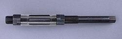
High Speed Steel Duplex Chucking Reamer with a Straight Shank
Chucking reamers, or machine reamers, are the most common type of reamer used in lathes, drill presses, and screw machines that provide a smooth finish to the hole. They come in a variety of flutes and cuts (e.g. right hand cut, left hand spiral, straight flute) as well as different shank types. Chucking reamers can be manufactured with a straight shank or morse taper shank.[2]
Adjustable hand reamer
Adjustable hand reamer
An adjustable hand reamer can cover a small range of sizes. They are generally referenced by a letter which equates to a size range. The disposable blades slide along a tapered groove. The act of tightening and loosening the restraining nuts at each end varies the size that may be cut. The absence of any spiral in the flutes restricts them to light usage (minimal material removal per setting) as they have a tendency to chatter. They are also restricted to usage in unbroken holes. If a hole has an axial split along it, such as a split bush or a clamping hole, each straight tooth will in turn drop into the gap causing the other teeth to retract from their cutting position. This also gives rise to chatter marks and defeats the purpose of using the reamer to size a hole.
Straight reamer
A straight reamer is used to make only a minor enlargement to a hole. The entry end of the reamer will have a slight taper, the length of which will depend on its type. This produces a self centering action as it enters the raw hole. The larger proportion of the length will be of a constant diameter.
Reamed holes are used to create holes of precise circularity and size, for example with tolerances of -0/+0.02mm(.0008") This will allow the force fitting of locating dowel pins, which need not be otherwise retained in the body holding them. Other holes, reamed slightly larger in other parts, will fit these pins accurately, but not so tightly as to make disassembly difficult. This type of alignment is common in the joining of split crankcase halves such as are used in motorcycle motors and boxer type engines. After joining the halves, the assembled case may then be line bored (using what is in effect a large diameter reamer), and then disassembled for placement of bearings and other parts. The use of reamed dowel holes is typical in any machine design, where any two locating parts have to be located and mated accurately to one another - typically as indicated above, to within 0.02mm or less than .001".
Another use of reamed holes is to receive a specialized bolt that has an unthreaded shoulder - also called a shoulder bolt. This type of bolt is commonly used to replace hot peened rivets during the seismic retrofit of structures.
Hand reamer
A hand reamer has a longer taper or lead in at the front than a machine reamer. This is to compensate for the difficulty of starting a hole by hand power alone. It also allows the reamer to start straight and reduce the risk of breakage. The flutes may be straight or spiral.
Machine reamer
Spiral fluted machine reamer
A machine reamer only has a very slight lead in. Because the reamer and work piece are pre-aligned by the machine there is no risk of it wandering off course. In addition the constant cutting force that can be applied by the machine ensures that it starts cutting immediately. Spiral flutes have the advantage of clearing the swarf automatically but are also available with straight flutes as the amount of swarf generated during a reaming operation should be very small.
Rose reamer
A rose reamer has no relief on the periphery and is offset by a front taper to prevent binding. They are secondarily used as softing reamers.
Shell reamer
Shell reamers are designed for reaming bearing and other similar items. They are fluted almost their whole length.
Tapered reamer
Four small tapered pin reamers
A precision tapered reamer is used to make a tapered hole to later receive a tapered pin. A taper pin is a self tightening device due to the shallow angle of the taper. They may be driven into the tapered hole such that removal can only be done with a hammer and punch. They are sized by a number sequence (for example, a No.4 reamer would use No.4 taper pins). Such precision joints are used in aircraft assembly and are frequently used to join the two or more wing sections used in a sailplane. These may be re-reamed one or more times during the aircraft's useful life, with an appropriately oversized pin replacing the previous pin.
Morse taper reamer
No. 3 morse taper reamer
A morse taper reamer is used manually to finish morse taper sleeves. These sleeves are a tool used to hold machine cutting tools or holders in the spindles of machines such as a drill or milling machine. The reamer shown is a finishing reamer. A roughing reamer would have serrations along the flutes to break up the thicker chips produced by the heavier cutting action used for it.
Combination reamer
This combination reamer was made for a long run, tight tolerance electronic parts.
A combination reamer has two or more cutting surfaces. The combination reamer is precision ground into a pattern that resembles the part's multiple internal diameters. The advantage of using a combination reamer is to reduce the number of turret operations, while more precisely holding depths, internal diameters and concentricity. Combination reamers are mostly used in screw machines or second-operation lathes, not with Computer Numerical Control (CNC) machines because G-code can be easily generated to profile internal diameters.
Combination reamers can be made out of cobalt, carbide, or high speed steel tooling. When using combination reamers to ream large internal diameters made out of material with lower surface feet per minute, carbide tips can be brazed onto a configured drill blank to build the reamer. Carbide requires additional care because it is very brittle and will chip if chatter occurs. It is common to use a drill bit or combination drill to remove the bulk of material to reduce wear, or the risk of the part pulling off on the combination reamer.
Tapered reamer (non-precision)
A tapered reamer
A tapered reamer may be used for cleaning burrs from a drilled hole, or to enlarge a hole. The body of the tool tapers to a point. This type of reamer consists of a body which, typically, is up to 1/2inch in diameter, with a rod cross piece at the large end acting to form a handle. It is especially useful for working softer metals such as aluminum, copper, and mild steel. Another name for it is "maintenance reamer", referring to its use in the miscellaneous deburring and enlarging tasks often found in MRO work. A similar tool can be seen on select Swiss Army knives, such as the electrician model, to be used on conduit.
Process
To achieve highly accurate and consistent diameters with a reamer, one must consider process variables that can influence the overall quality of the hole being reamed. Variables such as reamer material, reamer design, material being reamed, temperature at the reamed surface, reamer speed, machine or operator movement, etc. must be addressed. By controlling these variables to the best extent possible, the reaming process can easily produce highly accurate and consistently sized holes.
Reamers should not be reversed in use as this will tend to dull the cutting edges.[3]
Size – accuracy and repeatability
The final hole size that is achieved by a reamer subsequently depends on the reaming process being used in conjunction with the reamer design and materials involved. Studies have been conducted which demonstrate the effect of coolant use during reaming.[4] The continuous use of a coolant stream during the reaming process has been shown to consistently (75% of the time) result in hole sizes that are 0.0001 in. (0.0025mm) larger than the reamer itself, with a process spread of +/- 0.0002 in. the remainder of the time. Similarly, using a semi-wet reaming process often results in hole sizes that are 0.0004 in. larger than the reamer itself, approximately 60% of the time, with a process spread of 0.0006 in. favoring an increase in size. Dry reaming should be discouraged due to its low level of repeatability (20%) in size and wide process spread of sizes up to 0.0012 in. (0.030mm) larger than the reamer size.
Surface finish and longevity
When properly designed and used, reamers can experience an extended service life of up to 30,000 holes.[5] A properly controlled process is also capable of maintaining a consistent size down the entire length of the hole while minimizing the hour-glass effect. Reamed holes may typically have a surface finish of 10 to 25μin (250 to 640nm)Ra.
Setup and equipment
Generally, reaming is done using a drill press. However, lathes, machining centers and similar machines can be used as well. The workpiece is firmly held in place by either a vise, chuck or fixture while the reamer advances.[6]
Tool materials
Like other cutting tools, there are two categories of materials used to build reamers: heat treated and hard. Heat treated materials are composed by different steels, most notably plain carbon (unalloyed, considered obsolete today) and high-speed steels. The most common hard material is tungsten carbide (solid or tipped), but reamers with edges of cubic boron nitride (CBN) or diamond also exist.[6]
The main difference between both categories is that hard materials are usually unaffected by the heat produced by the machining process and may actually benefit from it. The down side is that they are usually very brittle, requiring slightly blunt cutting edges to avoid fracture. This increases the forces involved in machining and for this reason hard materials are usually not recommended for light machinery. Heat treated materials, on the other side, are usually much tougher and have no problem holding a sharp edge without chipping under less favourable conditions (like under vibration). This makes them adequate for hand tools and light machines.[6]
Common tool materials
Applications
High-speed steels
Most commonly used. Inexpensive.
Hardness up to HRC 67. Sharp cutting edges, meaning less cutting force.
The high cobalt versions are very resistant to heat and thus excellent for reaming abrasive and/or work hardening materials such as titanium and stainless steel.
Tungsten carbide
More expensive than high-speed steels.
Hardness up to HRC 92. Will outlast high-speed steels (usually by about 10:1) when reaming steel.
Required to ream hardened materials.
Cast aluminium (due to high silicon content).
Workpiece materials
Aluminum and brass are typical workpieces with good to excellent machinability ratings. Cast iron, mild steel and plastic have good ratings. Stainless steel has a poor rating because of its toughness and it tends to work harden as it is machined.[6]
Lubrication
During the process of reaming friction causes the part and the tool to heat up. Proper lubrication cools the tool, which increases the life of the tool. Another benefit of lubrication includes higher cutting speeds. This decreases production times. Lubrication also removes chips and contributes to a better workpiece finish. Mineral oils, synthetic oils, and water-soluble oils are used for lubrication and applied by flooding or spraying. In the case of some materials only cold air is needed to cool the workpiece. This is applied by air jet[6] or vortex tube.[7]
Work Material
Cutting Fluid
Application
Aluminum
Soluble oil, kerosene, synthetic fluid
Flood
Brass
None, soluble oil
Flood
Cast Iron
Cold air, none
Air jet
Mild steel
Soluble oil, sulfurized oil
Flood
Stainless steel
Soluble oil, sulfurized oil
Flood
Plastics
None, mineral oil, synthetic oil
Flood, spray
Related standards
National and international standards are used to standardize the definitions and classifications used for reamers (either based on construction or based on method of holding or driving). Selection of the standard to be used is an agreement between the supplier and the user and has some significance in the design of the reamer. In the United States, ASME has developed the B94.2 Standard, which establishes requirements methods for specifying the classification of reamers.[8]
This page is based on this Wikipedia article Text is available under the CC BY-SA 4.0 license; additional terms may apply. Images, videos and audio are available under their respective licenses.