Vernier scale

Last updated
Vernier caliper scales; main at top, vernier at bottom. It reads 3.58 +- 0.02 mm by adding 3.00 mm (left red mark) on the fixed main scale to vernier 0.58 mm (right red mark). The main scale reading is that to the left of the zero on the vernier scale. The vernier reading is found by locating the best aligned lines between the two scales. The 0.02 mm engraving indicates the caliper's readability and is the "vernier constant" for this scale. Close up of vernier scale.jpg
Vernier caliper scales; main at top, vernier at bottom. It reads 3.58 ± 0.02 mm by adding 3.00 mm (left red mark) on the fixed main scale to vernier 0.58 mm (right red mark). The main scale reading is that to the left of the zero on the vernier scale. The vernier reading is found by locating the best aligned lines between the two scales. The 0.02 mm engraving indicates the caliper's readability and is the "vernier constant" for this scale.

A vernier scale, named after Pierre Vernier, is a visual aid to take an accurate measurement reading between two graduation markings on a linear scale by using mechanical interpolation, thereby increasing resolution and reducing measurement uncertainty by using vernier acuity to reduce human estimation error. It may be found on many types of instrument measuring linear or angular quantities, but in particular on a vernier caliper, which measures lengths (including internal and external diameters).

Contents

The vernier is a subsidiary scale replacing a single measured-value pointer, and has for instance ten divisions equal in distance to nine divisions on the main scale. The interpolated reading is obtained by observing which of the vernier scale graduations is coincident with a graduation on the main scale, which is easier to perceive than visual estimation between two points. Such an arrangement can go to a higher resolution by using a higher scale ratio, known as the vernier constant. A vernier may be used on circular or straight scales where a simple linear mechanism is adequate. Examples are calipers and micrometers to measure to fine tolerances, on sextants for navigation, on theodolites in surveying, and generally on scientific instruments. The Vernier principle of interpolation is also used for electronic displacement sensors such as absolute encoders to measure linear or rotational movement, as part of an electronic measuring system.

History

The first caliper with a secondary scale, which contributed extra precision, was invented in 1631 by French mathematician Pierre Vernier (15801637). [1] Its use was described in detail in English in Navigatio Britannica (1750) by mathematician and historian John Barrow. [2] While calipers are the most typical use of vernier scales today, they were originally developed for angle-measuring instruments such as astronomical quadrants.

In some languages, the vernier scale is called a nonius after Portuguese mathematician and cosmographer Pedro Nunes (Latin Petrus Nonius, 1502–1578). In English, this term was used until the end of the 18th century. [3] Nonius now refers to an earlier instrument that Nunes developed.

The name "vernier" was popularised by the French astronomer Jérôme Lalande (1732–1807) through his Traité d'astronomie (2 vols) (1764). [4]

Functioning

Vernier caliper with a vernier constant of 0.1 for clarity of operation. The standard for a caliper is usually a constant of 0.02 VernierscaleHow a vernier scale works.gif
Vernier caliper with a vernier constant of 0.1 for clarity of operation. The standard for a caliper is usually a constant of 0.02
Vernier caliper scale with the normal 0.02 vernier constant, showing measurement of object at 19.44 mm to two decimal places Vernier scale use 0.02 scale measurement is 19.44 mm.gif
Vernier caliper scale with the normal 0.02 vernier constant, showing measurement of object at 19.44 mm to two decimal places

The use of the vernier scale is shown on a vernier caliper which measures the internal and the external diameters of an object.

The vernier scale is constructed so that it is spaced at a constant fraction of the fixed main scale. So for a vernier with a constant of 0.1, each mark on the vernier is spaced 9/10 of those on the main scale. If you put the two scales together with zero points aligned, the first mark on the vernier scale is 1/10 short of the first main scale mark, the second is 2/10 short, and so on up to the ninth mark, which is misaligned by 9/10. Only when a full ten marks are counted, is there alignment, because the tenth mark is 10/10—a whole main scale unit—short, and therefore aligns with the ninth mark on the main scale. (In simple words, each VSD = 0.9 MSD, so each decrement of length 0.1 adds 10 times to make one MSD only in 9 divisions of vernier scale division).

Now if you move the vernier by a small amount, say, 1/10 of its fixed main scale, the only pair of marks that come into alignment are the first pair, since these were the only ones originally misaligned by 1/10. If we move it 2/10, the second pair aligns, since these are the only ones originally misaligned by that amount. If we move it 5/10, the fifth pair aligns—and so on. For any movement, only one pair of marks aligns and that pair shows the value between the marks on the fixed scale.

Least count or vernier constant

The difference between the value of one main scale division and the value of one vernier scale division is known as the least count of the vernier, also known as the vernier constant. Let the measure of the smallest main-scale reading, that is the distance between two consecutive graduations (also called its pitch) be S, and the distance between two consecutive vernier scale graduations be V, such that the length of (n  1) main-scale divisions is equal to n vernier-scale divisions. Then

the length of (n − 1) main-scale divisions = the length of n vernier-scale division, or
(n − 1)S = nV, or
nSS = nV.

Vernier acuity

Vernier scales work so well because most people are especially good at detecting which of the lines is aligned and misaligned, and that ability gets better with practice, in fact far exceeding the optical capability of the eye. This ability to detect alignment is called vernier acuity . [5] Historically, none of the alternative technologies exploited this or any other hyperacuity, giving the vernier scale an advantage over its competitors. [6]

Zero error

Zero error is defined as the condition where a measuring instrument registers a reading when there should not be any reading. In case of vernier calipers it occurs when a zero on main scale does not coincide with a zero on vernier scale. The zero error may be of two types: when the scale is towards numbers greater than zero, it is positive; otherwise it is negative. The method to use a vernier scale or caliper with zero error is to use the formula

actual reading = main scale + vernier scale − (zero error).

Zero error may arise due to knocks or other damage which causes the 0.00 mm marks to be misaligned when the jaws are perfectly closed or just touching each other.

Vernier micrometer reading 5.783 +- 0.001 mm, comprising 5.5 mm on main screw lead scale, 0.28 mm on screw rotation scale, and 0.003 mm added from vernier. 5783metric-micrometer.jpg
Vernier micrometer reading 5.783 ± 0.001 mm, comprising 5.5 mm on main screw lead scale, 0.28 mm on screw rotation scale, and 0.003 mm added from vernier.
When the jaws are closed and if the reading is 0.10 mm, the zero error is referred to as +0.10 mm. The method to use a vernier scale or caliper with zero error is to use the formula 'actual reading = main scale + vernier scale - (zero error)' thus the actual reading is 19.00 + 0.54 - (0.10) = 19.44 Vernier scale zero error +0.10.gif
When the jaws are closed and if the reading is 0.10 mm, the zero error is referred to as +0.10 mm. The method to use a vernier scale or caliper with zero error is to use the formula 'actual reading = main scale + vernier scale − (zero error)' thus the actual reading is 19.00 + 0.54 − (0.10) = 19.44

Positive zero error refers to the case when the jaws of the vernier caliper are just closed and the reading is a positive reading away from the actual reading of 0.00 mm. If the reading is 0.10 mm, the zero error is referred to as +0.10 mm.

Negative zero error refers to the case when the jaws of the vernier caliper are just closed and the reading is a negative reading away from the actual reading of 0.00 mm. If the reading is 0.08 mm, the zero error is referred to as −0.08 mm.

If positive, the error is subtracted from the mean reading the instrument reads. Thus if the instrument reads 4.39 cm and the error is +0.05, the actual length will be 4.39 − 0.05 = 4.34. If negative, the error is added to the mean reading the instrument reads. Thus if the instrument reads 4.39 cm and as above the error is −0.05 cm, the actual length will be 4.39 + 0.05 = 4.44. (Considering that, the quantity is called zero correction which should always be added algebraically to the observed reading to the correct value.)

Zero error (ZE) = ±n × least count (LC)

Direct and retrograde verniers

Direct verniers are the most common. The indicating scale is constructed so that when its zero point coincides with the start of the data scale, its graduations are at a slightly smaller spacing than those on the data scale and so none but the last graduation coincide with any graduations on the data scale. N graduations of the indicating scale cover N  1 graduations of the data scale.

Retrograde verniers are found on some devices, including surveying instruments. [7] A retrograde vernier is similar to the direct vernier, except its graduations are at a slightly larger spacing than on the main scale. N graduations of the indicating scale cover N + 1 graduations of the data scale. The retrograde vernier also extends backwards along the data scale.

Direct and retrograde verniers are read in the same manner.

Recent uses

This section includes references to techniques which use the Vernier principle to make fine-resolution measurements.

Vernier spectroscopy is a type of cavity-enhanced laser absorption spectroscopy that is especially sensitive to trace gases. The method uses a frequency-comb laser combined with a high-finesse optical cavity to produce an absorption spectrum in a highly parallel manner. The method is also capable of detecting trace gases in very low concentration due to the enhancement effect of the optical resonator on the effective optical path length. [8]

See also

Related Research Articles

<span class="mw-page-title-main">Sextant</span> Tool for angle measurement

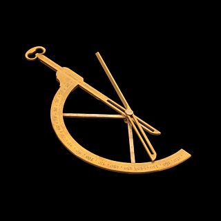
A sextant is a doubly reflecting navigation instrument that measures the angular distance between two visible objects. The primary use of a sextant is to measure the angle between an astronomical object and the horizon for the purposes of celestial navigation.

<span class="mw-page-title-main">Micrometer (device)</span> Tool for the precise measurement of a components length, width, and/or depth

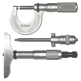
A micrometer, sometimes known as a micrometer screw gauge, is a device incorporating a calibrated screw widely used for accurate measurement of components in mechanical engineering and machining as well as most mechanical trades, along with other metrological instruments such as dial, vernier, and digital calipers. Micrometers are usually, but not always, in the form of calipers. The spindle is a very accurately machined screw and the object to be measured is placed between the spindle and the anvil. The spindle is moved by turning the ratchet knob or thimble until the object to be measured is lightly touched by both the spindle and the anvil.

Significant figures, also referred to as significant digits or sig figs, are specific digits within a number written in positional notation that carry both reliability and necessity in conveying a particular quantity. When presenting the outcome of a measurement, if the number of digits exceeds what the measurement instrument can resolve, only the number of digits within the resolution's capability are dependable and therefore considered significant.

<span class="mw-page-title-main">Visual acuity</span> Clarity of vision

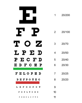
Visual acuity (VA) commonly refers to the clarity of vision, but technically rates an animal's ability to recognize small details with precision. Visual acuity depends on optical and neural factors. Optical factors of the eye influence the sharpness of an image on its retina. Neural factors include the health and functioning of the retina, of the neural pathways to the brain, and of the interpretative faculty of the brain.

<span class="mw-page-title-main">Pierre Vernier</span> French mathematician

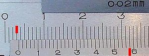
Pierre Vernier was a French mathematician and instrument inventor. He was the inventor and eponym of the vernier scale used in measuring devices.

<span class="mw-page-title-main">Goniometer</span> Angle measuring instrument

A goniometer is an instrument that either measures an angle or allows an object to be rotated to a precise angular position. The term goniometry derives from two Greek words, γωνία (gōnía) 'angle' and μέτρον (métron) 'measure'. The protractor is a commonly used type in the fields of mechanics, engineering, and geometry.

<span class="mw-page-title-main">Calipers</span> Tool used to measure dimensions of an object

Caliper(s) or calliper(s) are an instrument used to measure the dimensions of an object; namely, the diameter or depth of a hole. The word caliper comes from latin roots meaning precise pincer.

<span class="mw-page-title-main">Indicator (distance amplifying instrument)</span> Distance amplifying instrument

In various contexts of science, technology, and manufacturing, an indicator is any of various instruments used to accurately measure small distances and angles, and amplify them to make them more obvious. The name comes from the concept of indicating to the user that which their naked eye cannot discern; such as the presence, or exact quantity, of some small distance.

A bore gauge is a collective term for the tools that are unique to the process of accurately measuring holes.

<span class="mw-page-title-main">Linear encoder</span>

A linear encoder is a sensor, transducer or readhead paired with a scale that encodes position. The sensor reads the scale in order to convert the encoded position into an analog or digital signal, which can then be decoded into position by a digital readout (DRO) or motion controller.

A thousandth of an inch is a derived unit of length in a system of units using inches. Equal to 11000 of an inch, a thousandth is commonly called a thou or, particularly in North America, a mil.

<span class="mw-page-title-main">Least count</span> Smallest value a measuring instrument can measure

In the science of measurement, the least count of a measuring instrument is the smallest value in the measured quantity that can be resolved on the instrument's scale. The least count is related to the precision of an instrument; an instrument that can measure smaller changes in a value relative to another instrument, has a smaller "least count" value and so is more precise. Any measurement made by the instrument can be considered repeatable to no less than the resolution of the least count. The least count of an instrument is inversely proportional to the precision of the instrument.

<span class="mw-page-title-main">Diameter at breast height</span> Standard method of expressing the diameter of the trunk or bole of a standing tree

Diameter at breast height, or DBH, is a standard method of expressing the diameter of the trunk or bole of a standing tree. DBH is one of the most common dendrometric measurements.

A level staff, also called levelling rod, is a graduated wooden or aluminium rod, used with a levelling instrument to determine the difference in height between points or heights of points above a vertical datum. When used for stadiametric rangefinding, the level staff is called a stadia rod.

<span class="mw-page-title-main">Dividing engine</span>

A dividing engine is a device employed to mark graduations on measuring instruments.

<span class="mw-page-title-main">Transversal (instrument making)</span>

Transversals are a geometric construction on a scientific instrument to allow a graduation to be read to a finer degree of accuracy. Their use creates what is sometimes called a diagonal scale, an engineering measuring instrument which is composed of a set of parallel straight lines which are obliquely crossed by another set of straight lines. Diagonal scales are used to measure small fractions of the unit of measurement.

Reflecting instruments are those that use mirrors to enhance their ability to make measurements. In particular, the use of mirrors permits one to observe two objects simultaneously while measuring the angular distance between the objects. While reflecting instruments are used in many professions, they are primarily associated with celestial navigation as the need to solve navigation problems, in particular the problem of the longitude, was the primary motivation in their development.

<span class="mw-page-title-main">Elton's quadrant</span>

An Elton's quadrant is a derivative of the Davis quadrant. It adds an index arm and artificial horizon to the instrument, and was invented by English sea captain John Elton, who patented his design in 1728 and published details of the instrument in the Philosophical Transactions of the Royal Society in 1732.

<span class="mw-page-title-main">Nonius (device)</span>

Nonius is a measuring tool used in navigation and astronomy named in honour of its inventor, Pedro Nunes, a Portuguese author, mathematician and navigator. The nonius was created in 1542 as a system for taking finer measurements on circular instruments such as the astrolabe. The system was eventually adapted into the Vernier scale in 1631 by the French mathematician Pierre Vernier.

<span class="mw-page-title-main">Philadelphia rod</span>

A Philadelphia rod is a level staff used in surveying. The rod is used in levelling procedures to determine elevations and is read using a level.

References

  1. Vernier, Pierre (1631). La Construction, l'Usage et les Propriétez du Quadrant Nouveau de Mathématique [The Construction, Use, and Properties of the New Mathematical Quadrant] (in French). Brussels, (Belgium): Francois Vivien.
  2. Barrow called the device a Vernier scale. See: John Barrow, Navigatio britannica: or a complete system of navigation ... (London, England: W. and J. Mount and T. Page, 1750), pp. 140–142, especially page 142.
  3. Daumas, Maurice, Scientific Instruments of the Seventeenth and Eighteenth Centuries and Their Makers, Portman Books, London 1989 ISBN   978-0-7134-0727-3
  4. Lalande, Jérôme (1764), Astronomie, vol. 2 (Paris, France: Desaint & Saillant), pages 859-860.
  5. Vernier acuity definition at the Online Medical Dictionary.
  6. Kwan, A. (2011). "Vernier scales and other early devices for precise measurement". American Journal of Physics. 79 (4): 368–373. Bibcode:2011AmJPh..79..368K. doi:10.1119/1.3533717.
  7. Davis, Raymond, Foote, Francis, Kelly, Joe, Surveying, Theory and Practice, McGraw-Hill Book Company, 1966, LC 64-66263.
  8. Feng Zhu; James Bounds; Aysenur Bicer; James Strohaber; Alexandre A. Kolomenskii; Christoph Gohle; Mahmood Amani; Hans A. Schuessler (2014). "Near infrared frequency comb vernier spectrometer for broadband trace gas detection". Opt. Express. 22 (19): 23026–23033. arXiv: 1407.1075 . Bibcode:2014OExpr..2223026Z. doi:10.1364/OE.22.023026. PMID   25321773. S2CID   119270139.