System for producing precision lengths by stacking components
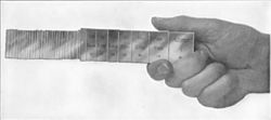
Metric gauge block set, 112 pcsAnother set with 8 pcs, 125 mm - 500 mmTrolley model
Gauge blocks (also known as gage blocks, Johansson gauges, slip gauges, or Jo blocks) are a system for producing precision lengths. The individual gauge block is a metal or ceramic block that has been precision ground and lapped to a specific thickness. Gauge blocks come in sets of blocks with a range of standard lengths. In use, the blocks are stacked to make up a desired length (or height).
An important feature of gauge blocks is that they can be joined together with very little dimensional uncertainty. The blocks are joined by a sliding process called wringing, which causes their ultra-flat surfaces to cling together. A small number of gauge blocks can be used to create accurate lengths within a wide range. By using three blocks at a time taken from a set of 30 blocks, one may create any of the 1000 lengths from 3.000 to 3.999mm in 0.001mm steps (or .3000 to .3999 inches in 0.0001inch steps).
Description
How gauge blocks are measured.
A gauge block is a block of metal or ceramic with two opposing faces ground precisely flat and parallel, a precise distance apart. Standard grade blocks are made of a hardened steel alloy, while calibration grade blocks are often made of tungsten carbide (WC), chromium carbide (CrC) or ceramic (SiO2-based) because they are harder and wear less.[2] Gauge blocks come in sets of blocks of various lengths, along with additional wear blocks, to allow a wide variety of standard lengths to be made up by stacking them. The length of each block is actually slightly shorter than the nominal length stamped on it, because the stamped length includes the length of one wring film, a film of lubricant which separates adjacent block faces in normal use. The thickness of the wring film is about 25 nanometers (0.98μin).[3] The gauge's nominal length is also known as the interferometric length.[4]
In use, the blocks are removed from the set, cleaned of their protective coating (petroleum jelly or oil) and wrung together to form a stack of the required dimension. Gauge blocks are calibrated to be accurate at 20°C (68°F) and should be kept at this temperature when taking measurements. This mitigates the effects of thermal expansion. The wear blocks, made of a harder substance like tungsten carbide, are included at each end of the stack, whenever possible, to protect the gauge blocks from being damaged in use.
Machinists and toolmakers try to use a stack with the fewest blocks to avoid accumulation of size errors. For example, a stack totaling .638 that is composed of two blocks (a .500 block wrung to a .138 block) is preferable to a stack also totaling .638 that is composed of four blocks (such as a .200, .149, .151, and .138 all wrung together). Each block has a size tolerance of a few millionths of an inch, so stacking them together introduces a cumulative uncertainty (as detailed in §Grades below). However, the stacked error from even multiple blocks is usually negligible in all but the most demanding uses. In a busy shop, some of the blocks will be in use elsewhere, so one creates a stack from the blocks available at the time. Typically the few millionths of an inch difference will not be detectable, or matter, in the context. Contexts demanding ultimate precision are rarer and require additional expense (for example, more sets of blocks and higher grades of blocks).
Wringing is the process of sliding two blocks together so that their faces bond. Because of their ultraflat surfaces, when wrung, gauge blocks adhere to each other tightly. Properly wrung blocks may withstand a 300N (67lbf) pull.[5] The mechanism is a combination of:[4][5][needs update]
Vacuum applies pressure between the blocks because the air is squeezed out of the joint[note 1]
Molecular attraction that occurs when two very flat surfaces are brought into contact; this force causes gauge blocks to adhere even without surface lubricants, and in a vacuum
36 Johansson gauge blocks wrung together easily support their own weight.
It is believed that the last two sources are the most significant.[4] Experiments with friction of the blocks suggest also that the removal of the oxide film from the steel surface by wringing plays an important role in the wringing action.[7]
There is no magnetism involved, although to a user the clinging together of the blocks feels a bit like weak refrigerator magnets sticking together. Unlike magnets, however, the cling only lasts while the blocks are completely joined—the blocks do not attract each other across any visible gap, as magnets would.
Wiping any extra oil off the gauge block using a dry pad.
The block is then slid perpendicularly across the other block while applying moderate pressure until they form a cruciform.
Finally, the block is rotated until it is inline with the other block.
After use, the blocks are re-oiled or greased to protect against corrosion. The ability of a given gauge block to wring is called wringability; it is officially defined as "the ability of two surfaces to adhere tightly to each other in the absence of external means." The minimum conditions for wringability are a surface finish of 1 microinch (0.025μm)AA or better, and a flatness of at least 5μin (0.13μm).[4]
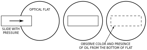
There is a formal test to measure wringability. First, the block is prepared for wringing using the standard process. The block is then slid across a 2in (51mm) reference grade (1μin[0.025μm] flatness) quartz optical flat while applying moderate pressure. Then, the bottom of the gauge block is observed (through the optical flat) for oil or color. For Federal Grades 0.5, 1, and 2 and ISO grades K, 00, and 0 no oil or color should be visible under the gauge block. For Federal Grade 3 and ISO grades 1 and 2, no more than 20% of the surface area should show oil or color. This test is hard to perform on gauge blocks thinner than 0.1in (2.5mm) because they tend not to be flat in the relaxed state.[4]
Accessories
A gauge block accessory setA holder that turns a stack of gauge blocks into an instant, custom caliper or go/no go gauge.
The pictured accessories provide a set of holders and tools to extend the usefulness of the gauge block set. They provide a means of securely clamping large stacks together, along with reference points, scribers, and various shapes of blocks that act like caliper jaws, either external or internal. Conical-tip ones ease measurement of center-to-center distances between hole centers. A stack of gauge blocks with external caliper-jaw accessories, all clamped together, acts as a quickly assembled custom-size go or no-go gauge.
A special gauge block stone that cannot damage the surface is used to remove nicks and burrs to maintain wringability.[4]
There are two wringing pads used to prepare a gauge block for wringing. The first is an oil pad, which applies a light layer of oil to the block. The second is a dry pad, which removes any excess oil from the block after the oil pad has been used.[4]
Grades
Gauge blocks (left in each picture, under optical flat) being used to measure the height of a ball bearing and a plug gage using interferometry. The interference fringes (lines) visible on the surface of the flats indicates error; the number of lines indicates the amount.
Gauge blocks are available in various grades, depending on their intended use.[8] The grading criterion is tightness of tolerance on their sizes; thus higher grades are made to tighter tolerances and have higher accuracy and precision. Various grading standards include: JIS B 7506-1997 (Japan)/DIN 861-1980 (Germany), ASME (US), BS 4311: Part 1: 1993 (UK). Tolerances will vary within the same grade as the thickness of the material increases.
reference (AAA): small tolerance (±0.05μm or ±1.97μin) used to establish standards
calibration (AA): (tolerance +0.10 to −0.05μm or +3.94 to −1.97μin) used to calibrate inspection blocks and very high precision gauging
inspection (A): (tolerance +0.15 to −0.05μm or +5.91 to −1.97μin) used as toolroom standards for setting other gauging tools
workshop (B): large tolerance (tolerance +0.25 to −0.15μm or +9.84 to −5.91μin) used as shop standards for precision measurement
More recent grade designations include (US Federal Specification GGG-G-15C):
0.5 – generally equivalent to grade AAA
1 – generally equivalent to grade AA
2 – generally equivalent to grade A+
3 – compromise grade between A and B
and ANSI/ASME B89.1.9M, which defines both absolute deviations from nominal dimensions and parallelism limits as criteria for grade determination. Generally, grades are equivalent to former US Federal grades as follows:
00 – generally equivalent to grade 1 (most exacting flatness and accuracy requirements)
0 – generally equivalent to grade 2
AS-1 – generally equivalent to grade 3 (reportedly stands for American Standard - 1)
AS-2 – generally less accurate than grade 3
K – generally equivalent to grade 00 flatness (parallelism) with grade AS-1 accuracy
The ANSI/ASME standard follows a similar philosophy as set forth in ISO 3650. See the NIST reference below for more detailed information on tolerances for each grade and block size. Also consult page E-4 of: Commercial Gauge Block Tolerances (Length refers to the calibrated thickness)
Manufacture
Gauge blocks are usually made either from hardened alloy tool steels, ceramics or cemented carbides (such as tungsten carbide or tantalum carbide). Often the carbide has a hardness of 1500 Vickers hardness. Long series blocks are made from high-quality steel having cross section (35×9mm) with holes for clamping two slips together. These are also available in carbon steel material. Steel blocks are hardened and tempered. The hardness is important because it slows down the gauge's rate of wear during use (this is why other kinds of gauges, such as pins, thread plugs, and rings, are also hardened.) The cutting of the blocks to size is accomplished with grinding followed by lapping. Usually no plating or other coating is involved. Blocks are kept very lightly oiled, and are stored and used in dry climate-controlled conditions; unplated, uncoated steel gauge blocks can last for decades without rusting.
History
The gauge block set, also known as "Jo Blocks", was developed by the Swedish inventor Carl Edvard Johansson.[9] Johansson was employed in 1888 as an armourer inspector by the state arsenalCarl Gustafs stads Gevärsfaktori (Rifle Factory of Carl Gustaf's town) in the town of Eskilstuna, Sweden. He was concerned with the expensive tools for measuring parts for the Remington rifles then in production under licence at Carl Gustaf. When Sweden adopted a tailored variant of the Mauser carbine in 1894, Johansson was very excited about the chance to study Mauser's methods of measuring, in preparation for production under license at Carl Gustaf (which began several years later). However, a visit to the Mauser factory in Oberndorf am Neckar, Germany, turned out to be a disappointment. On the train home, he thought about the problem, and he came up with the idea of a set of blocks that could be combined to make up any measure.
There had already been a long history of increasing use of gauges up to this time, such as gauges for filing and go/no go gauges, which were custom-made individually in a toolroom for use on the shop floor; but there had never been super-precision gauge blocks that could be wrung together to make up different lengths, as Johansson now envisioned.
Back home, Johansson converted his wife's Singer sewing machine to a grinding and lapping machine. He preferred to carry out this precision work at home, as the grinding machines at the rifle factory were not good enough. His wife, Margareta, helped him with the initial prototyping. Once Johansson had demonstrated his set at Carl Gustaf, his employer provided time and resources for him to develop the idea. Johansson was granted his first Swedish patent on 2 May 1901, SE patent No. 17017, called "Gauge Block Sets for Precision Measurement". Johansson formed the Swedish company CE Johansson AB (also known as 'CEJ') on 16 March 1917.
Johansson spent many years in America; during his life he crossed the Atlantic 22 times.[citation needed] The first CEJ gauge block set in America was sold to Henry M. Leland at the Cadillac Automobile Company around 1908. The first manufacturing plant in America for his gauge block sets was established in Poughkeepsie, Dutchess County, New York, in 1919. The economic environment of the post–World War I recession and depression of 1920–21 did not turn out so well for the company, so in 1923 he wrote a letter to Henry Ford of the Ford Motor Company, where he proposed a cooperation in order to save his company. Henry Ford became interested, and on 18 November 1923 he began working for Henry Ford in Dearborn, Michigan. Hounshell (1984), citing Althin (1948) and various archive primary sources, says, "Henry Ford purchased the famous gaugemaking operation of the Swede C.E. Johansson in 1923 and soon moved it into the laboratory facility in Dearborn. Between 1923 and 1927, the Johansson division supplied 'Jo-blocks' to the Ford toolroom and any manufacturer who could afford them. It also made some of the Ford 'go' and 'no-go' gauges used in production as well as other precision production devices."[10]
In the early 20th century, the US inch was effectively defined as 25.4000508mm (with a reference temperature of 68°F [20°C]) and the UK inch at 25.399977mm (with a reference temperature of 62°F [17°C]).[11] When Johansson started manufacturing gauge blocks in inch sizes in 1912, Johansson's compromise was to manufacture gauge blocks with a nominal size of 25.4mm, with a reference temperature of 20°C (68°F), accurate to within a few parts per million of both official definitions. Because Johansson's blocks were so popular, his blocks became the de facto standard for manufacturers internationally,[11][12] with other manufacturers of gauge blocks following Johansson's definition by producing blocks designed to be equivalent to his.[13]
In 1930, the British Standards Institution adopted an inch of exactly 25.4mm. The American Standards Association followed suit in 1933. By 1935, industry in 16 countries had adopted the "industrial inch" as it came to be known,[14][15] effectively endorsing Johansson's pragmatic choice of conversion ratio.[11]
Co-branding of CEJ, Ford, and B&S logos.
In 1936, at the age of 72, Johansson felt it was time to retire and go back to Sweden. He was awarded the large gold medal of the Royal Swedish Academy of Engineering Sciences in 1943, shortly after his death.
In 1948 Brown & Sharpe bought the rights to the C.E. Johansson brand from Ford Motor Co.,[16] and blocks co-branded with the C.E. Johansson and Brown & Sharpe logos were made. Blocks co-branded with the C.E. Johansson and Ford logos are also sometimes still seen in use today.
Gauge pins
Similar to gauge blocks, these are precision-ground cylindrical bars, for use as plug gauges to measure hole diameters, or as parts of go/no go gauges or similar applications.
↑ Breki, A.; Nosonovsky, M. (2023). "Friction and adhesion of Johansson gauge blocks". Surface Innovations. 11 (1–2): 18–22. doi:10.1680/jsuin.22.01083.
This page is based on this Wikipedia article Text is available under the CC BY-SA 4.0 license; additional terms may apply. Images, videos and audio are available under their respective licenses.