Optical flats in case. About 2.5 centimetres (1in) in diameter. The third flat from the left is standing on edge, showing the thickness.A λ/20 optical flat that has been coated with aluminum, making a first-surface mirrorTwo optical flats tested using 589 nm laser-light. At 2 inches (5.1cm) in diameter and 0.5 inches (13mm) thick, both surfaces are flat to within 1/10 of the wavelength of the light (58.9 nm), as indicated by the perfectly straight fringes.
An optical flat is an optical-grade piece of glasslapped and polished to be extremely flat on one or both sides, usually within a few tens of nanometres (billionths of a metre). They are used with a monochromatic light to determine the flatness (surface accuracy) of other surfaces (whether optical, metallic, ceramic, or otherwise), by means of wave interference.[1]
When an optical flat is placed on another surface and illuminated, the light waves reflect off both the bottom surface of the flat and the surface it is resting on. This causes a phenomenon similar to thin-film interference. The reflected waves interfere, creating a pattern of interference fringes visible as light and dark bands. The spacing between the fringes is smaller where the gap is changing more rapidly, indicating a departure from flatness in one of the two surfaces. This is comparable to the contour lines one would find on a map. A flat surface is indicated by a pattern of straight, parallel fringes with equal spacing, while other patterns indicate uneven surfaces. Two adjacent fringes indicate a difference in elevation of one-half wavelength of the light used, so by counting the fringes, differences in elevation of the surface can be measured to better than one micrometre.
Usually only one of the two surfaces of an optical flat is made flat to the specified tolerance, and this surface is indicated by an arrow on the edge of the glass. Optical flats are sometimes given an optical coating and used as precision mirrors or optical windows for special purposes, such as in a Fabry–Pérot interferometer or laser cavity. Optical flats have uses in spectrophotometry as well.
Flatness testing
Testing the flatness of surfaces with optical flats. The lefthand surface is flat; the righthand surface is astigmatic, with curvatures in two orthogonal directions.An optical flat test in which the angular size of the light source is too small. The interference fringes only show up in the reflection, so the light needs to appear larger than the flat.
An optical flat is usually placed upon a flat surface to be tested. If the surface is clean and reflective enough, rainbow colored bands of interference fringes will form when the test piece is illuminated with white light. However, if a monochromatic light is used to illuminate the work piece, such as helium, low-pressure sodium, or a laser, then a series of dark and light interference fringes will form. These interference fringes determine the flatness of the work piece, relative to the optical flat, to within a fraction of the wavelength of the light. If both surfaces are perfectly the same flatness and parallel to each other, no interference fringes will form. However, there is usually some air trapped between the surfaces. If the surfaces are flat, but a tiny optical wedge of air exists between them, then straight, parallel interference fringes will form, indicating the angle of the wedge (i.e.: more, thinner fringes indicate a steeper wedge while fewer but wider fringes indicate less of a wedge). The shape of the fringes also indicate the shape of the test surface, because fringes with a bend, a contour, or rings indicate high and low points on the surface, such as rounded edges, hills or valleys, or convex and concave surfaces.[2]
Preparation
Both the optical flat and the surface to be tested need to be extremely clean. The tiniest bit of dust settling between the surfaces can ruin the results. Even the thickness of a streak or a fingerprint on the surfaces can be enough to change the width of the gap between them. Before the test, the surfaces are usually cleaned very thoroughly. Most commonly, acetone is used as the cleaning agent, because it dissolves most oils and it evaporates completely, leaving no residue. Typically, the surface will be cleaned using the "drag" method, in which a lint-free, scratch-free tissue is wetted, stretched, and dragged across the surface, pulling any impurities along with it. This process is usually performed dozens of times, ensuring that the surface is completely free of impurities. A new tissue will need to be used each time, to prevent recontamination of the surfaces from previously removed dust and oils.
Testing is often done in a clean-room or another dust-free environment, keeping the dust from settling on the surfaces between cleaning and assembly. Sometimes, the surfaces may be assembled by sliding them together, helping to scrape off any dust that might happen to land on the flat. The testing is usually done in a temperature-controlled environment to prevent any distortions in the glass, and needs to be performed on a very stable work-surface. After testing, the flats are usually cleaned again and stored in a protective case, and are often kept in a temperature-controlled environment until used again.
Lighting
For the best test-results, a monochromatic light, consisting of only a single wavelength, is used to illuminate the flats. To show the fringes properly, several factors need to be taken into account when setting up the light source, such as the angle of incidence between the light and the observer, the angular size of the light source in relation to the pupil of the eye, and the homogeneity of the light source when reflected off of the glass.
Many sources for monochromatic light can be used. Most lasers emit light of a very narrow bandwidth, and often provide a suitable light source. A helium–neon laser emits light at 632 nanometres (red), while a frequency doubledNd:YAG laser emits light at 532nm (green). Various laser diodes and diode-pumped solid-state lasers emit light in red, yellow, green, blue or violet. Dye lasers can be tuned to emit nearly any color. However, lasers also experience a phenomenon called laser speckle, which shows up in the fringes.
Several gas or metal-vapor lamps can also be used. When operated at low pressure and current, these lamps generally produce light in various spectral lines, with one or two lines being most predominant. Because these lines are very narrow, the lamps can be combined with narrow-bandwidth filters to isolate the strongest line. A helium-discharge lamp will produce a line at 587.6nm (yellow), while a mercury-vapor lamp produces a line at 546.1 (yellowish green). Cadmium vapor produces a line at 643.8nm (red), but low pressure sodium produces a line at 589.3nm (yellow). Of all the lights, low pressure sodium is the only one that produces a single line, requiring no filter.
The fringes only appear in the reflection of the light source, so the optical flat must be viewed from the exact angle of incidence that the light shines upon it. If viewed from a zero degree angle (from directly above), the light must also be at a zero degree angle. As the viewing angle changes, the lighting angle must also change. The light must be positioned so that its reflection can be seen covering the entire surface. Also, the angular size of the light source needs to be many times greater than the eye. For example, if an incandescent light is used, the fringes may only show up in the reflection of the filament. By moving the lamp much closer to the flat, the angular size becomes larger and the filament may appear to cover the entire flat, giving clearer readings. Sometimes, a diffuser may be used, such as the powder coating inside frosted bulbs, to provide a homogenous reflection off the glass. Typically, the measurements will be more accurate when the light source is as close to the flat as possible, but the eye is as far away as possible.[3]
How interference fringes form
How interference works. The distance between the bright fringe (a) and the dark fringe (b) indicates a change in the light path length of 1/2 the wavelength, so a change of the width of the gap of 1/4 wavelength. So the distance between two bright or dark fringes indicates a change in the gap of 1/2 wavelength. The gap between the surfaces and the wavelength of the light waves are greatly exaggerated.
The diagram shows an optical flat resting on a surface to be tested. Unless the two surfaces are perfectly flat, there will be a small gap between them (shown), which will vary with the contour of the surface. Monochromatic light (red) shines through the glass flat and reflects from both the bottom surface of the optical flat and the top surface of the test piece, and the two reflected rays combine and superpose. However, the ray reflecting off the bottom surface travels a longer path. The additional path length is equal to twice the gap between the surfaces. In addition, the ray reflecting off the bottom surface undergoes a 180° phase reversal, while the internal reflection of the other ray from the underside of the optical flat causes no phase reversal. The brightness of the reflected light depends on the difference in the path length of the two rays:
Constructive interference: In areas where the path length difference between the two rays is equal to an odd multiple of half a wavelength (λ/2) of the light waves, the reflected waves will be in phase, so the "troughs" and "peaks" of the waves coincide. Therefore, the waves will reinforce (add) and the resulting light intensity will be greater. As a result, a bright area will be observed there.
Destructive interference: At other locations, where the path length difference is equal to an even multiple of a half-wavelength, the reflected waves will be 180° out of phase, so a "trough" of one wave coincides with a "peak" of the other wave. Therefore, the waves will cancel (subtract) and the resulting light intensity will be weaker or zero. As a result, a dark area will be observed there.'
If the gap between the surfaces is not constant, this interference results in a pattern of bright and dark lines or bands called "interference fringes" being observed on the surface. These are similar to contour lines on maps, revealing the height differences of the bottom test surface. The gap between the surfaces is constant along a fringe. The path length difference between two adjacent bright or dark fringes is one wavelength of the light, so the difference in the gap between the surfaces is one-half wavelength. Since the wavelength of light is so small, this technique can measure very small departures from flatness. For example, the wavelength of red light is about 700nm, so the difference in height between two fringes is half that, or 350nm, about 1/100 the diameter of a human hair.
Mathematical derivation
The variation in brightness of the reflected light as a function of gap width can be found by deriving the formula for the sum of the two reflected waves. Assume that the z-axis is oriented in the direction of the reflected rays. Assume for simplicity that the intensity A of the two reflected light rays is the same (this is almost never true, but the result of differences in intensity is just a smaller contrast between light and dark fringes). The equation for the electric field of the sinusoidal light ray reflected from the top surface traveling along the z-axis is
where is the peak amplitude, λ is the wavelength, and is the angular frequency of the wave. The ray reflected from the bottom surface will be delayed by the additional path length and the 180° phase reversal at the reflection, causing a phase shift with respect to the top ray
where is the phase difference between the waves in radians. The two waves will superpose and add: the sum of the electric fields of the two waves is
This represents a wave at the original wavelength whose amplitude is proportional to the cosine of , so the brightness of the reflected light is an oscillating, sinusoidal function of the gap width d. The phase difference is equal to the sum of the phase shift due to the path length difference 2d and the additional 180° phase shift at the reflection
so the electric field of the resulting wave will be
This represents an oscillating wave whose magnitude varies sinusoidally between and zero as increases.
Constructive interference: The brightness will be maximum where , which occurs when
Destructive interference: The brightness will be zero (or in the more general case minimum) where , which occurs when
Thus the bright and dark fringes alternate, with the separation between two adjacent bright or dark fringes representing a change in the gap length of one half wavelength (λ/2).
Precision and errors
Two λ/10 flats at 589nm. Although both surfaces have some irregularities, the test shows they are both flat relative to each other. As wringing progresses the thin fringes widen until only a single fringe remains.A thermal image of an optical flat after handling for just a few seconds. The warmer areas increase the thickness of the flat over cooler areas, distorting the surface accordingly.
Counterintuitively, the fringes do not exist within the gap or the flat itself. The interference fringes actually form when the light waves all converge at the eye or camera, forming the image. Because the image is the compilation of all converging wavefronts interfering with each other, the flatness of the test piece can only be measured relative to the flatness of the optical flat. Any deviations on the flat will be added to the deviations on the test surface. Therefore, a surface polished to a flatness of λ/4 cannot be effectively tested with a λ/4 flat, as it is not possible to determine where the errors lie, but its contours can be revealed by testing with more accurate surfaces like a λ/20 or λ/50 optical flat. This also means that both the lighting and viewing angle have an effect on the accuracy of the results. When lighted or viewed at an angle, the distance that the light must travel across the gap is longer than when viewed and illuminated straight on. Thus, as the angle of incidence becomes steeper, the fringes will also appear to move and change. A zero degree angle of incidence is usually the most desirable angle, both for lighting and viewing. Unfortunately, this is usually impossible to achieve with the naked eye. Many interferometers use beamsplitters to obtain such an angle. Because the results are relative to the wavelength of the light, accuracy can also be increased by using light of shorter wavelengths, although the 632nm line from a helium–neon laser is often used as the standard.[4]
No surface is ever completely flat. Therefore, any errors or irregularities that exist on the optical flat will affect the results of the test. Optical flats are extremely sensitive to temperature changes, which can cause temporary surface deviations resulting from uneven thermal expansion. The glass often experiences poor thermal conduction, taking a long time to reach thermal equilibrium. Merely handling the flats can transfer enough heat to offset the results, so glasses such as fused silica or borosilicate are used, which have very low coefficients of thermal expansion. The glass needs to be hard and very stable, and is usually very thick to prevent flexing. When measuring on the nanometre scale, the slightest bit of pressure can cause the glass to flex enough to distort the results. Therefore, a very flat and stable work-surface is also needed, on which the test can be performed, preventing both the flat and the test-piece from sagging under their combined weight, Often, a precision-ground surface plate is used as a work surface, providing a steady table-top for testing upon. To provide an even flatter surface, sometimes the test may be performed on top of another optical flat, with the test surface sandwiched in the middle.
Absolute flatness
Absolute flatness is the flatness of an object when measured against an absolute scale, in which the reference flat (standard) is completely free of irregularities. The flatness of any optical flat is relative to the flatness of the original standard that was used to calibrate it. Therefore, because both surfaces have some irregularities, there are few ways to know the true, absolute flatness of any optical flat. The only surface that can achieve nearly absolute flatness is a liquid surface, such as mercury, and can sometimes achieve flatness readings to within λ/100, which equates to a deviation of only 6.32nm (632nm/100). However, liquid flats are very difficult to use and align properly, so they are typically only used when preparing a standard flat for calibrating other flats.[5]
The other method for determining absolute flatness is the "three-flat test." In this test, three flats of equal size and shape are tested against each other. By analyzing the patterns and their different phase shifts, the absolute contours of each surface can be extrapolated. This usually requires at least twelve individual tests, checking each flat against every other flat in at least two different orientations. To eliminate any errors, the flats sometimes may be tested while resting on edge, rather than lying flat, helping to prevent sagging.[6][7]
Wringing occurs when nearly all of the air becomes forced out from between the surfaces, causing the surfaces to lock together, partly through the vacuum between them. The flatter the surfaces; the better they will wring together, especially when the flatness extends all the way to the edges. If two surfaces are very flat, they may become wrung together so tightly that a lot of force may be needed to separate them.
The interference fringes typically only form once the optical flat begins to wring to the testing surface. If the surfaces are clean and very flat, they will begin to wring almost immediately after the first contact. After wringing begins, as air is slowly forced out from between the surfaces, an optical wedge forms between the surfaces. The interference fringes form perpendicular to this wedge. As the air is forced out, the fringes will appear to move toward the thickest gap, spreading out and becoming wider but fewer. As the air is forced out, the vacuum holding the surfaces together becomes stronger. The optical flat should usually never be allowed to fully wring to the surface, otherwise it can be scratched or even broken when separating them. In some cases, if left for many hours, a block of wood may be needed to knock them loose. Testing flatness with an optical flat is typically done as soon a viable interference pattern develops, and then the surfaces are separated before they can fully wring. Because the angle of the wedge is extremely shallow and the gap extremely small, wringing may take a few hours to complete. Sliding the flat in relation to the surface can speed up wringing, but trying to press the air out will have little effect.
If the surfaces are insufficiently flat, if any oil films or impurities exist on the surface, or if slight dust-particles land between the surfaces, they may not wring at all. Therefore, the surfaces must be very clean and free of debris to get an accurate measurement.[8]
Determining surface shape
Initial wringing, 532 nm,
Initial wringing, white light,
Wringing, 1 hour,
Wringing, 2 hours,
Fully wrung,
Fully wrung in white light. The window is slightly concave rather than convex.
A flatness test of a float-glassoptical window. By placing a ruler across the image, adjacent to a fringe, and counting how many fringes cross it, the flatness of the surface can be measured along any line. The window has a flatness of 4–6λ (~2100–3100nm) per inch.An optical flat test in both green and red. The wavelengths are nearly harmonic opposites (green is λ/4 shorter), so the fringes overlap every fourth red-fringe (every fifth green-fringe), interfering to form yellow fringes.
The fringes act very much like the lines on a topography map, where the fringes are always perpendicular to the wedge between the surfaces. When wringing first begins, there is a large angle in the air wedge and the fringes will resemble grid topography-lines. If the fringes are straight; then the surface is flat. If the surfaces are allowed to fully wring and become parallel, the straight fringes will widen until only a dark fringe remains, and they will disappear completely. If the surface is not flat, the grid lines will have some bends in them, indicating the topography of the surface. Straight fringes with bends in them may indicate a raised elevation or a depression. Straight fringes with a "V" shape in the middle indicate a ridge or valley running across the center, while straight fringes with curves near the ends indicate edges that are either rounded-off or have a raised lip.
If the surfaces are not completely flat, as wringing progresses the fringes will widen and continue to bend. When fully wrung, they will resemble contour topography-lines, indicating the deviations on the surface. Rounded fringes indicate gentle sloping or slightly cylindrical surfaces, while tight corners in the fringes indicate sharp angles in the surface. Small, round circles may indicate bumps or depressions, while concentric circles indicate a conical shape. Unevenly spaced concentric circles indicate a convex or concave surface. Before the surfaces fully wring, these fringes will be distorted due to the added angle of the air wedge, changing into the contours as the air is slowly pushed out.
A single dark-fringe has the same gap thickness, following a line that runs the entire length of the fringe. The adjacent bright-fringe will indicate a thickness which is either 1/2 of the wavelength narrower or 1/2 of the wavelength wider. The thinner and closer the fringes are; the steeper the slope is, while wider fringes, spaced further apart, show a shallower slope. Unfortunately, it is impossible to tell whether the fringes are indicating an uphill or downhill slope from just a single view of the fringes alone, because the adjacent fringes can be going either way. A ring of concentric circles can indicate that the surface is either concave or convex, which is an effect similar to the hollow-mask illusion.
There are three ways to test the surface for shape, but the most common is the "finger-pressure test." In this test, slight pressure is applied to the flat, to see which way the fringes move. The fringes will move away from the narrow end of the wedge. If the testing surface is concave, when pressure is applied to the center of the rings, the flat will flex a little and the fringes will appear to move inward. However, if the surface is convex, the flat will be in point-contact with the surface in that spot, so it will have no room to flex. Thus, the fringes will remain stationary, merely growing a little wider. If pressure is applied to the edge of the flat something similar happens. If the surface is convex the flat will rock a little, causing the fringes to move toward the finger. However, if the surface is concave the flat will flex a little, and the fringes will move away from the finger toward the center. Although this is called a "finger" pressure test, a wooden stick or some other instrument is often used to avoid heating the glass (with the mere weight of a toothpick often being enough pressure).
Another method involves exposing the flat to white light, allowing rainbow fringes to form, and then pressing in the center. If the surface is concave, there will be point-contact along the edge, and the outer fringe will turn dark. If the surface is convex, there will be point-contact in the center, and the central fringe will turn dark. Much like tempering colors of steel, the fringes will be slightly brownish at the narrower side of the fringe and blue on the wider side, so if the surface is concave the blue will be on the inside of the rings, but if convex the blue will be on the outside.
The third method involves moving the eye in relation to the flat. When moving the eye from a zero-degree angle of incidence to an oblique angle, the fringes will appear to move. If the testing surface is concave, the fringes will appear to move toward the center. If the surface is convex, the fringes will move away from the center. To get a truly accurate reading of the surface, the test should usually be performed in at least two different directions. As grid lines, the fringes only represent part of a grid, so a valley running across the surface may only show as a slight bend in the fringe if it is running parallel to the valley. However, if the optical flat is rotated 90 degrees and retested, the fringes will run perpendicular to the valley and it will show up as a row of V- or U-shaped contours in the fringes. By testing in more than one orientation, a better map of the surface can be made.[9]
Long-term stability
During reasonable care and use, optical flats need to maintain their flatness over long periods of time. Therefore, hard glasses with low coefficients of thermal expansion, such as fused silica, are often used for the manufacturing material. However, a few laboratory measurements of room temperature, fused-silica optical-flats have shown a motion consistent with a material viscosity on the order of 1017–1018Pa·s.[10] This equates to a deviation of a few nanometres over the period of a decade. Because the flatness of an optical flat is relative to the flatness of the original test flat, the true (absolute) flatness at the time of manufacture can only be determined by performing an interferometer test using a liquid flat, or by performing a "three flat test", in which the interference patterns produced by three flats are computer-analyzed. A few tests that have been carried out have shown that a deviation sometimes occurs on the fused silica's surface. However, the tests show that the deformation may be sporadic, with only some of the flats deforming during the test period, some partially deforming, and others remaining the same. The cause of the deformation is unknown and would never be visible to the human eye during a lifetime. (A λ/4 flat has a normal surface-deviation of 158 nanometres, while a λ/20 flat has a normal deviation of over 30nm.) This deformation has only been observed in fused silica, while soda-lime glass still shows a viscosity of 1041Pa·s, which is many orders of magnitude higher.[11]
Diffraction is the interference or bending of waves around the corners of an obstacle or through an aperture into the region of geometrical shadow of the obstacle/aperture. The diffracting object or aperture effectively becomes a secondary source of the propagating wave. Italian scientist Francesco Maria Grimaldi coined the word diffraction and was the first to record accurate observations of the phenomenon in 1660.
In physics, interference is a phenomenon in which two coherent waves are combined by adding their intensities or displacements with due consideration for their phase difference. The resultant wave may have greater intensity or lower amplitude if the two waves are in phase or out of phase, respectively. Interference effects can be observed with all types of waves, for example, light, radio, acoustic, surface water waves, gravity waves, or matter waves as well as in loudspeakers as electrical waves.
In optics, the refractive index of an optical medium is a dimensionless number that gives the indication of the light bending ability of that medium.
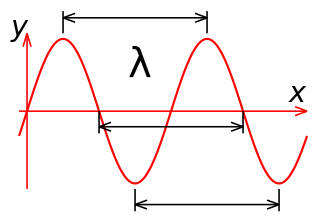
In physics and mathematics, wavelength or spatial period of a wave or periodic function is the distance over which the wave's shape repeats. In other words, it is the distance between consecutive corresponding points of the same phase on the wave, such as two adjacent crests, troughs, or zero crossings. Wavelength is a characteristic of both traveling waves and standing waves, as well as other spatial wave patterns. The inverse of the wavelength is called the spatial frequency. Wavelength is commonly designated by the Greek letter lambda (λ). The term "wavelength" is also sometimes applied to modulated waves, and to the sinusoidal envelopes of modulated waves or waves formed by interference of several sinusoids.
In physics, a standing wave, also known as a stationary wave, is a wave that oscillates in time but whose peak amplitude profile does not move in space. The peak amplitude of the wave oscillations at any point in space is constant with respect to time, and the oscillations at different points throughout the wave are in phase. The locations at which the absolute value of the amplitude is minimum are called nodes, and the locations where the absolute value of the amplitude is maximum are called antinodes.
Fourier optics is the study of classical optics using Fourier transforms (FTs), in which the waveform being considered is regarded as made up of a combination, or superposition, of plane waves. It has some parallels to the Huygens–Fresnel principle, in which the wavefront is regarded as being made up of a combination of spherical wavefronts whose sum is the wavefront being studied. A key difference is that Fourier optics considers the plane waves to be natural modes of the propagation medium, as opposed to Huygens–Fresnel, where the spherical waves originate in the physical medium.
In optics, the Fraunhofer diffraction equation is used to model the diffraction of waves when plane waves are incident on a diffracting object, and the diffraction pattern is viewed at a sufficiently long distance from the object, and also when it is viewed at the focal plane of an imaging lens. In contrast, the diffraction pattern created near the diffracting object and is given by the Fresnel diffraction equation.
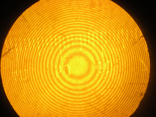
Newton's rings is a phenomenon in which an interference pattern is created by the reflection of light between two surfaces, typically a spherical surface and an adjacent touching flat surface. It is named after Isaac Newton, who investigated the effect in 1666. When viewed with monochromatic light, Newton's rings appear as a series of concentric, alternating bright and dark rings centered at the point of contact between the two surfaces. When viewed with white light, it forms a concentric ring pattern of rainbow colors because the different wavelengths of light interfere at different thicknesses of the air layer between the surfaces.
The shearing interferometer is an extremely simple means to observe interference and to use this phenomenon to test the collimation of light beams, especially from laser sources which have a coherence length which is usually significantly longer than the thickness of the shear plate so that the basic condition for interference is fulfilled.
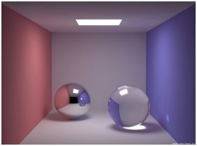
Gloss is an optical property which indicates how well a surface reflects light in a specular (mirror-like) direction. It is one of the important parameters that are used to describe the visual appearance of an object. Other categories of visual appearance related to the perception of regular or diffuse reflection and transmission of light have been organized under the concept of cesia in an order system with three variables, including gloss among the involved aspects. The factors that affect gloss are the refractive index of the material, the angle of incident light and the surface topography.
In physics, a Bragg plane is a plane in reciprocal space which bisects a reciprocal lattice vector, , at right angles. The Bragg plane is defined as part of the Von Laue condition for diffraction peaks in x-ray diffraction crystallography.
Antenna measurement techniques refers to the testing of antennas to ensure that the antenna meets specifications or simply to characterize it. Typical parameters of antennas are gain, bandwidth, radiation pattern, beamwidth, polarization, and impedance.
In electromagnetics, directivity is a parameter of an antenna or optical system which measures the degree to which the radiation emitted is concentrated in a single direction. It is the ratio of the radiation intensity in a given direction from the antenna to the radiation intensity averaged over all directions. Therefore, the directivity of a hypothetical isotropic radiator is 1, or 0 dBi.
Acousto-optics is a branch of physics that studies the interactions between sound waves and light waves, especially the diffraction of laser light by ultrasound through an ultrasonic grating.
Free spectral range (FSR) is the spacing in optical frequency or wavelength between two successive reflected or transmitted optical intensity maxima or minima of an interferometer or diffractive optical element.
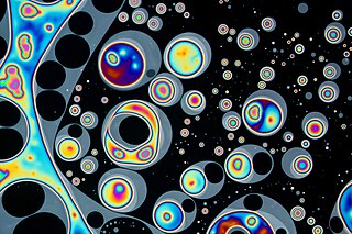
Thin-film interference is a natural phenomenon in which light waves reflected by the upper and lower boundaries of a thin film interfere with one another, increasing reflection at some wavelengths and decreasing it at others. When white light is incident on a thin film, this effect produces colorful reflections.
Kirchhoff's diffraction formula approximates light intensity and phase in optical diffraction: light fields in the boundary regions of shadows. The approximation can be used to model light propagation in a wide range of configurations, either analytically or using numerical modelling. It gives an expression for the wave disturbance when a monochromatic spherical wave is the incoming wave of a situation under consideration. This formula is derived by applying the Kirchhoff integral theorem, which uses the Green's second identity to derive the solution to the homogeneous scalar wave equation, to a spherical wave with some approximations.
In optics, the Fraunhofer diffraction equation is used to model the diffraction of waves when the diffraction pattern is viewed at a long distance from the diffracting object, and also when it is viewed at the focal plane of an imaging lens.
As described here, white light interferometry is a non-contact optical method for surface height measurement on 3D structures with surface profiles varying between tens of nanometers and a few centimeters. It is often used as an alternative name for coherence scanning interferometry in the context of areal surface topography instrumentation that relies on spectrally-broadband, visible-wavelength light.
Optical holography is a technique which enables an optical wavefront to be recorded and later re-constructed. Holography is best known as a method of generating three-dimensional images but it also has a wide range of other applications.
↑ Tool and Manufacturing Engineers Handbook by W. H. Cubberly, Ramon Bakerjian – Society of Manufacturing Engineers 1989Page 12-13
↑ Optical Shop Testing by Daniel Malacara – John Wiley and Sons 2009 Page 5–9
↑ Vannoni, M.; Sordoni, A.; Molesini, G. (2011). "Relaxation time and viscosity of fused silica glass at room temperature". European Physical Journal E. 34 (9): 9–14. doi:10.1140/epje/i2011-11092-9. PMID21947892. S2CID2246471.
This page is based on this Wikipedia article Text is available under the CC BY-SA 4.0 license; additional terms may apply. Images, videos and audio are available under their respective licenses.