Base end station

Last updated

Base end stations were used by the United States Army Coast Artillery Corps as part of fire control systems for locating the positions of attacking ships and controlling the firing of seacoast guns, mortars, or mines to defend against them. [1] A British equivalent was the position finding cell. [2]

Contents

Types of base end stations

A "true" base end station was one of a pair of stations at either end of a precisely measured (surveyed) baseline. [note 1] [3] Once simultaneous bearings from each base end station to a target were taken, since the distance between the stations (the baseline) was known, the range to the target from either station could be calculated through triangulation. If the target's bearing from each station was sent to a plotting room and input to a plotting board, the position of the target could be estimated and firing coordinates for a gun battery could be calculated.

Some base end stations were located in tall fire control towers (FCTs) [note 2] Sometimes, the terms "base end station" and "fire control tower" were used interchangeably. In general, however, a fire control tower (FCT) was a structure built to raise one or more base end, spotting, or observation stations high above ground level. Some fire control towers contained several base end stations, one on top of another on different stories of the tower, with each station being at one end of a different baseline and being assigned primarily to a different gun battery in a harbor's defensive scheme. Other base end stations resembled pillboxes or small bunkers dug into the ground or on the surface overlooking coastal waters. Still others were camouflaged to resemble seaside homes or cottages. Some base end stations had anti-aircraft observation positions on their top levels, or harbor observation radar antennas on platforms above their roofs.

Typical equipment

Almost all base end stations were equipped at least with an azimuth telescope (similar to a surveyor's theodolite) to enable them to sight accurate bearings to a target. In addition, some base end stations held a depression position finder (DPF) or a coincidence range finder (CRF) that could be used by itself (without reference to another station) to produce fire control data for the gun(s). Sometimes a space holding one of these instruments (if not located on a baseline and paired with a second station) was referred to simply as an observation station.

These stations were used between the 1890s and 1946. At the end of the war almost all of them were declared surplus and were sold off to public and private owners. More than 100 of these stations still survive today on the coasts of the United States, as part of state preserves or under private ownership, although many have been razed to clear sites for new development.

Horizontal Base Systems

In a horizontal base system (like that in the diagram above), two base end stations were located at precisely surveyed points, [note 3] one at each end of a base line, or a line between them of known length and azimuth. [note 4] At each of these stations was an observation instrument (such as an azimuth telescope or a depression position finder (DPF) capable of making a precise measurement of the bearing of a distant target (usually a ship) from the station. When the stations at each end of the baseline had made their measurements, they communicated these to a plotting room (or fire control center) which used an analog tracking device called a plotting board to locate the position of the target. [note 5] Later in World War II, the target bearings could be input to an electro-mechanical gun data computer, which calculated the position of the target and the required adjustments for things like ballistic factors and the locations of the guns that were to be fired.

Making this system work properly required the two base end stations to take bearings on the target at precisely the same time. To enable this, a bell or buzzer (called the time-interval bell) was rung automatically at fixed intervals (usually every 15 or 20 seconds) in all observing stations across a harbor defense system [note 6] (note the dashed communications lines in the diagram above). One soldier, using the telescope or DPF, would track the target. At the sound of the bell, a second soldier would read the azimuth (at which the instrument was pointed) off a scale on the instrument and telephone this reading to the plotting room.

Spotting Stations

In World War II, each base end station was often combined with a spotting station. This meant that a second spotting instrument (usually an azimuth telescope) on a separate pedestal (or tripod) was included in the observing room, alongside the primary one (which was usually a depression position finder [DPF]).

A Depression Position Finder (on the left) and an Azimuth Scope at Fort Standish MA DPF and Azimuth Scope.jpg
A Depression Position Finder (on the left) and an Azimuth Scope at Fort Standish MA

While the primary observer (and perhaps the azimuth reader who assisted him) tracked the target, the role of the spotter was to observe the fall of fire from the guns of the supported battery, telephoning back to the plotting room whether the shells were falling short or over, left or right.

In harbor defense plans and other documents, such as survey data sheets prepared by the United States Coast and Geodetic Survey (USC&GS) and maintained by its successors, [4] these combined stations were often labeled according to the tactical numbers [note 7] of the gun batteries they were designed primarily to serve and their number in the series of stations serving that battery. Thus a station marked B 4/2 S 4/2 referred to base end station #4 for battery #2 and spotting station #4 for battery #2.

Vertical Base and Self-Contained Systems

These systems used instruments such as the depression position finder (DPF) or the coincidence rangefinder (CRF) to measure the range and/or azimuth to the target. [note 8]

Either of these two types of range finding stations could function effectively by itself, measuring both range and bearing (azimuth) to the target, without the need for a second base end station (as with the horizontal base system). Using one of these position-finding systems, while not as accurate as using the horizontal base method, had certain advantages. [note 9]

Some examples

Base end stations (also called observation stations) took a variety of forms. Some were multi-story fire control (FC) towers, either square or round in plan (or both), and rising from 20 to 100 feet above the ground. Some looked like forest fire watch towers. Others appeared to be small buildings, or were disguised as seaside cottages to camouflage their purpose. Still other base end stations resembled small pillboxes, dug into the ground, and usually positioned to look down on the channels they defended.

Base end stations were often assigned to particular batteries of guns or mine fields in a harbor defense system. In some U.S. harbors during WW2 there were 20 or more of these base end stations, often from 10,000 to 15,000 yards apart, and tied together by telephone lines running through switchboards. These stations could be used flexibly in different combinations or by different gun batteries as ships moved through the area, or in case a given station was damaged by enemy action.

Fire Control Towers (FCTs)

7-Story FCT at Point Allerton MA Pt Allerton FCT.jpg
7-Story FCT at Point Allerton MA
Ft. Miles Round FCT Ft-Miles-FCT.jpg
Ft. Miles Round FCT
Steel FCT, Ft. Story, VA Steel FCT.jpg
Steel FCT, Ft. Story, VA
Rear view of brick 2-story FCT from 1904 at Fort Andrews in Boston Harbor. East Side FC Station.jpg
Rear view of brick 2-story FCT from 1904 at Fort Andrews in Boston Harbor.
Front view of brick FCT at Ft. Andrews. East Side Station-Front.jpg
Front view of brick FCT at Ft. Andrews.
Emerson Point FCT
8-Story FCTs Nahant MA EmersonPointFCT.jpg
Emerson Point FCT
8-Story FCTs Nahant MA Twin FC towers.jpg
8-Story FCTs Nahant MA

Base End Stations (Lower Elevation)

Low base end station, Ft. Andrews west ridge. 1944 Base End Station.jpg
Low base end station, Ft. Andrews west ridge.
Base End Station Cottage in Minot MA Strawberry-Pt-Site-115-1D.jpg
Base End Station Cottage in Minot MA
Report of Completed Works Point Allerton MR Allerton BES radar.jpg
Report of Completed Works Point Allerton MR

DPF and CRF Stations

CRF Station at Fort Strong in Boston MA Basinger-CRF.jpg
CRF Station at Fort Strong in Boston MA
Mine Command Station at Fort Revere Mine BES.jpg
Mine Command Station at Fort Revere
Base End Station Diagram.jpg

See also

Notes

  1. This describes a horizontal base system. Vertical base systems, contained within a single instrument (and a single observation station), were also used.
  2. These towers could contain as many as 10 or more stories and rise 100 feet or more above the ground. Extra height greatly increased the range at which they could spot targets and the accuracy of their range estimates.
  3. The position of the station was usually measured (surveyed) as the "pintle center" or mounting point of its primary observation instrument.
  4. In this case, azimuth is synonymous with "direction" or "compass bearing." In the United States Army Coast Artillery Corps, azimuths were measured from south (instead of north) in a clockwise direction.
  5. Once this position was noted, it had to be converted to a set forward point, or the position the target was estimated to have reached at the time the shells fired would actually hit it. A number of other corrections also had to be made before the guns were pointed (in angle and azimuth). Corrected firing data included corrections for height of tide, wind direction and strength, atmospheric pressure, temperature, type of projectile fired, type and amount of powder used, etc.
  6. This bell also rang in the plotting room and at each gun in the battery. The cycle of bells governed the speed with which the plotting room crew had to work. If a gun did not receive "fresh" firing data by the end of a timing cycle, it had to wait until new data were received during a later timing cycle. For a fuller explanation, see the article on plotting boards.
  7. These numbers were assigned by the given harbor's Harbor Defense Command as part of its overall defense plan. Sometimes these numbers changed from year to year, for example if a formerly numbered gun was later not actually installed in its emplacement.
  8. Although the Coast Artillery used the "vertical base" and "self-contained" categories separately in its guidance, both types of systems were in fact self-contained, since either one could use a single observing instrument in a single observing station to accomplish its purpose.
  9. Most notably, the effectiveness of a horizontal base system depended on having both the widely separated stations watching (and taking bearings on) the same target, or ship. Under battle conditions, with a large group of attacking ships moving rapidly past the observing stations, perhaps under cover of a smokescreen or bad weather conditions, it might be difficult for the two stations to pick out the same target. Vertical base or self contained systems did not have this problem, although they did suffer from other drawbacks. The instruments used in these systems required better trained operators, were usually accurate to shorter ranges, and were more easily thrown off by fog or the "boiling" atmosphere caused by waves of heat rising up across the observed field.

Related Research Articles

<span class="mw-page-title-main">Indirect fire</span> Weapons firing without line of sight on target

Indirect fire is aiming and firing a projectile without relying on a direct line of sight between the gun and its target, as in the case of direct fire. Aiming is performed by calculating azimuth and inclination, and may include correcting aim by observing the fall of shot and calculating new angles.

<span class="mw-page-title-main">Fire-control system</span> Ranged weapon assistance system

A fire-control system (FCS) is a number of components working together, usually a gun data computer, a director and radar, which is designed to assist a ranged weapon system to target, track, and hit a target. It performs the same task as a human gunner firing a weapon, but attempts to do so faster and more accurately.

<span class="mw-page-title-main">Gun laying</span> Process of aiming an artillery piece or turret

Gun laying is the process of aiming an artillery piece or turret, such as a gun, howitzer, or mortar, on land, in air, or at sea, against surface or aerial targets. It may be laying for direct fire, where the gun is aimed similarly to a rifle, or indirect fire, where firing data is calculated and applied to the sights. The term includes automated aiming using, for example, radar-derived target data and computer-controlled guns.

<span class="mw-page-title-main">Fire control tower</span>

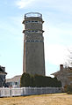
A fire control tower is a structure located near the coastline, used to detect and locate enemy vessels offshore, direct fire upon them from coastal batteries, or adjust the aim of guns by spotting shell splashes. Fire control towers came into general use in coastal defence systems in the late 19th century, as rapid development significantly increased the range of both naval guns and coastal artillery. This made fire control more complex. These towers were used in a number of countries' coastal defence systems through 1945, much later in a few cases such as Sweden. The Atlantic Wall in German-occupied Europe during World War II included fire control towers.

<span class="mw-page-title-main">Director (military)</span> Computer that calculates aiming for weapons

A director, also called an auxiliary predictor, is a mechanical or electronic computer that continuously calculates trigonometric firing solutions for use against a moving target, and transmits targeting data to direct the weapon firing crew.

East Point Military Reservation was a World War I and World War II coastal defense site located in Nahant, Massachusetts. In 1955–62 it was a Nike missile launch site. In 1967 the site was converted into the Marine Science Center of Northeastern University.

<span class="mw-page-title-main">Salisbury Beach Military Reservation</span>

Salisbury Beach Military Reservation was a coastal defense site located in Salisbury, Massachusetts.

<span class="mw-page-title-main">Battery 223</span> United States historic place

Battery 223 is in Lower Township, Cape May County, New Jersey, United States. The harbor defense battery was completed in 1943. It was added to the National Register of Historic Places on June 25, 2008.

<span class="mw-page-title-main">Fort Andrews</span>

Fort Andrews was created in 1897 as part of the Coast Defenses of Boston, Massachusetts. Construction began in 1898 and the fort was substantially complete by 1904. The fort was named after Major General George Leonard Andrews, an engineer and Civil War commander, who assisted in the construction of nearby Fort Warren in Boston Harbor. It occupies the entire northeast end of Peddocks Island in Boston Harbor, and was originally called the Peddocks Island Military Reservation. Once an active Coast Artillery post, it was manned by hundreds of soldiers and bristled with mortars and guns that controlled the southern approaches to Boston and Quincy Bay. The fort also served as a prisoner-of-war camp for Italian prisoners during World War II, who were employed as laborers following the Italian surrender to the Allies in 1943. Today, the fort is abandoned, and is managed by the Massachusetts Department of Conservation and Recreation, as part of the Boston Harbor Islands National Recreation Area.

A plotting board was a mechanical device used by the U.S. Army Coast Artillery Corps as part of their fire control system to track the observed course of a target, project its future position, and derive the uncorrected data on azimuth and range needed to direct the fire of the guns of a battery to hit that target. Plotting boards of this sort were first employed by the Coast Artillery around 1905, and were the primary means of calculating firing data until WW2. Towards the end of WW2 these boards were largely replaced by radar and electro-mechanical gun data computers, and were relegated to a back-up role.

<span class="mw-page-title-main">Plotting room</span>

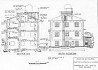
A plotting room was the co-ordination centre of a fire control system for guns used against enemy ships or aircraft, whether naval guns or coastal artillery. The plotting room received data on ship or aircraft position and motion from fire control instruments or their operators and determined and transmitted the range and bearing the guns would fire on. Plotting rooms came into use in the early 1900s for coastal artillery and during World War I for warships as gun ranges increased, and were in general use through the 1970s on World War II-era ships. Warships had plotting rooms for naval fire control for guns from 5-inch to 18-inch calibre, including anti-aircraft use for the smaller guns. On armoured ships such as battleships and cruisers, plotting rooms were located in the armoured citadel, protected by both deck and belt armour. With a few exceptions, coastal defence gun installations were inactivated shortly after World War II (US) through the middle 1950s (UK). Equipment in plotting rooms included specialised plotting boards and other analogue devices; by World War II these were supplemented or replaced by electro-mechanical gun data computers. Data could be received and transmitted by telephone, or directly via dedicated electrical systems. Locations of plotting rooms in coastal defence installations varied greatly; they could be in low-rise structures such as base end stations, taller fire control towers, in gun battery structures, or in bunkers separate from gun batteries.

<span class="mw-page-title-main">Coast Artillery fire control system</span>

In the U.S. Army Coast Artillery Corps, the term fire control system was used to refer to the personnel, facilities, technology and procedures that were used to observe designated targets, estimate their positions, calculate firing data for guns directed to hit those targets, and assess the effectiveness of such fire, making corrections where necessary.

<span class="mw-page-title-main">Directing point</span>

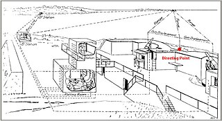
The directing point (DP) was a term used in the United States Army Coast Artillery Corps to identify a precisely surveyed point that was used as the point of reference for preparing the firing data used to aim the guns of a given Coast Artillery battery.

<span class="mw-page-title-main">Submarine mines in United States harbor defense</span>

The modern era of defending American harbors with controlled mines or submarine mines began in the post-Civil War period, and was a major part of US harbor defenses from circa 1900 to 1947.

<span class="mw-page-title-main">14-inch M1920 railway gun</span> Railway gun

The 14-inch M1920 railway gun was the last model railway gun to be deployed by the United States Army. It was an upgrade of the US Navy 14"/50 caliber railway gun. Only four were deployed; two in the Harbor Defenses of Los Angeles and two in the Panama Canal Zone, where they could be shifted between the harbor defenses of Cristobal (Atlantic) or Balboa (Pacific).

<span class="mw-page-title-main">Fort Ruckman</span>

Fort Ruckman was a U.S. Coast Artillery fort located in Nahant, Massachusetts. Originally called the Nahant Military Reservation, the fort was laid out in 1904-1907 and covered an area of about 45 acres just northwest of Bass Point, on the southwest side of the Nahant peninsula. During the 1920s, this area was renamed in honor of Maj. Gen. John Wilson Ruckman, a former Colonel in the Coast Artillery.

<span class="mw-page-title-main">12-inch coast defense mortar</span> American artillery

The 12-inch coast defense mortar was a weapon of 12-inch (305 mm) caliber emplaced during the 1890s and early 20th century to defend US harbors from seaborne attack. In 1886, when the Endicott Board set forth its initial plan for upgrading the coast defenses of the United States, it relied primarily on mortars, not guns, to defend American harbors. Over the years, provision was made for fortifications that would mount some 476 of these weapons, although not all of these tubes were installed. Ninety-one of these weapons were remounted as railway artillery in 1918-1919, but this was too late to see action in World War I. The railway mortars were only deployed in small quantities, and none overseas. The fixed mortars in the Philippines saw action in the Japanese invasion in World War II. All of the fixed mortars in the United States were scrapped by 1944, as new weapons replaced them, and the railway mortars were scrapped after the war. Today, the only remaining mortars of this type in the 50 states are four at Battery Laidley, part of Fort Desoto near St. Petersburg, Florida, but the remains of coast defense mortar emplacements can be seen at many former Coast Artillery forts across the United States and its former territories. Additional 12-inch mortars and other large-caliber weapons remain in the Philippines.

<span class="mw-page-title-main">Fort Foster (Kittery, Maine)</span>

Fort Foster, now part of Fort Foster Park, is a historic fort active 1901–1946 on the southwest tip of Gerrish Island in the Kittery Point area of Kittery, Maine. The park includes beaches and trails. Battery Bohlen and Battery Chapin were the major parts of the fort.

<span class="mw-page-title-main">Depression range finder</span>

The depression range finder (DRF) was a fire control device used to determine the target's position by observing range and bearing and to calculate firing solutions when gun laying in coastal artillery. It was the main component of a vertical base rangefinding system. It was necessitated by the introduction of rifled artillery from the mid-19th century onwards, which had much greater ranges than the old smoothbore weapons and were consequently more difficult to aim accurately. The DRF was invented by Captain H.S.S. Watkin of the Royal Artillery in the 1870s and was adopted in 1881. It could provide both range and bearing information on a target. The device's inventor also developed a family of similar devices, among them the position finder, which used two telescopes as a horizontal base rangefinding system, around the same time; some of these were called electric position finders. Some position finders retained a depression range finding capability; some of these were called depression position finders. Watkin's family of devices were deployed in position finding cells, a type of fire control tower, often in configurations that allowed both horizontal base and vertical base rangefinding. Watkin's system included automatic electrical updating of range and bearing dials near the guns as the position finders were manipulated, and a system of remotely firing the guns electrically from the position finding cell. The improved system was trialled in 1885 and widely deployed in the 1890s. Functionally equivalent devices were developed for the United States Army Coast Artillery Corps and its predecessors, called depression position finders or azimuth instruments depending on function, adopted in 1896 and deployed widely beginning in the early 1900s as the Endicott program of modern coastal defences was built. These devices were also used by both countries to control submarine (underwater) minefields.

References

  1. "FM 4-15, Seacoast Artillery fire control and position finding". Archived from the original on 2019-05-02. Retrieved 2019-05-02.
  2. Watkin depression position finders at victorianforts.co.uk
  3. Bolling W. Smith, "Vertical and Horizontal-Base Position Finding Systems," The Coast Defense Study Group Journal, Vol. 13, Issue 3, August, 1999.
  4. Sample data sheet for a base end station in Nahant, Massachusetts that was also a spotting station.