American soldiers using a coincidence rangefinder with its distinctive single eyepiece during army maneuvers in the 1940s.
A coincidence rangefinder or coincidence telemeter is a type of rangefinder that uses the principle of triangulation and an optical device to allow an operator to determine the distance to a visible object. There are subtypes split-image telemeter, inverted image, or double-image telemeter with different principles how two images in a single ocular are compared. Coincidence rangefinders were important elements of fire control systems for long-range naval guns and land-based coastal artillery circa 1890–1960. They were also used in rangefinder cameras.
A stereoscopic rangefinder looks similar, but has two eyepieces and uses a different principle, based on binocular vision. The two can normally be distinguished at a glance by the number of eyepieces.
Principle
Coincidence rangefinders work through the principle of triangulation. In the pictured example, triangulation can be used to determine the range of the ship 𝑑. The position of the lenses A and B are known, and the angle of the lenses α and/or β is set by the operator so that both are aimed at the target. Because the distance between A and B on a coincidence rangefinder is typically fixed, once the angle is set correctly the operator need only read the range from the scale.
Design
Schematic diagram of a coincidence range finder
The device consists of a long tube with a forward-facing lens at each end and an operator eyepiece in the center. Two prism wedges which, when aligned result in no deviation of the light, are inserted into the light path of one of the two lenses. By rotating the prisms in opposite directions using a differential gear, a degree of horizontal displacement of the image can be achieved.
Applications
Optical rangefinders using this principle, while applicable to several purposes, were widely used for military purposes—determining the range of a target—and for photographic use, determining the distance of a subject to photograph to allow focusing on it. Photographic rangefinders were initially accessories, from which the distance read off could be transferred to the camera's focusing mechanism; later they were built into rangefinder cameras, so that the image was in focus when the images were made to coincide.
Usage
Eyepiece image of a naval rangefinder, showing the displaced image when not yet adjusted for range
The coincidence rangefinder uses a single eyepiece. Light from the target enters the rangefinder through two windows located at either end of the instrument. At either side the incident beam is reflected to the center of the optical bar by a pentaprism. The optical bar is ideally made from a material with a low coefficient of thermal expansion so that optical path lengths do not change significantly with temperature. This reflected beam first passes through an objective lens and is then merged with the beam of the opposing side with an ocular prism sub-assembly to form two images of the target which are viewed by the observer through the eyepiece. Since either beam enters the instrument at a slightly different angle the resulting image, if unaltered, will appear blurry. Therefore, in one arm of the instrument a compensator is adjusted by the operator to tilt the beam until the two images match. At this point the images are said to be in coincidence. The degree of rotation of the compensator determines the range to the target by simple triangulation.[1] Coincidence rangefinders made by Barr and Stroud used two eyepieces, and may be confused with stereoscopic units. The second eyepiece showed the operator a range scale so the user could range and read the range scale simultaneously.[2][3]
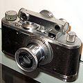
Coincidence telemeter on a Leica I
Rangefinder of the Polish destroyer ORP Wicher
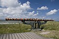
WW1 Coincidence rangefinder at Atlantikwall Raversyde, Belgium. Made by C.P. Goerz A.G. Berlin
Coincidence vs stereoscopic rangefinders
In November and December 1941, the United States National Defense Research Committee conducted extensive tests between the American Bausch and Lomb M1 stereoscopic rangefinder and the British Barr and Stroud FQ 25 and UB 7 coincidence rangefinders, and concluded "that the tests indicate no important difference in the precision obtainable from the two types of instrument — coincidence and stereoscopic. They do indicate, however, that the difference in performance between large and small instruments is by no means as great as would be anticipated from simple geometrical optics. The report concludes with the belief that stereoscopic and coincidence acuities are about equal. Under favourable conditions existing instruments of the two types perform about equally well, and the choice between them for any given purpose must be based on matters of convenience related to the particular conditions under which they are to be used."[4]
This page is based on this Wikipedia article Text is available under the CC BY-SA 4.0 license; additional terms may apply. Images, videos and audio are available under their respective licenses.