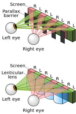
A parallax barrier is a device placed in front of an image source, such as a liquid crystal display, to allow it to show a stereoscopic or multiscopic image without the need for the viewer to wear 3D glasses. Placed in front of the normal LCD, it consists of an opaque layer with a series of precisely spaced slits, allowing each eye to see a different set of pixels, so creating a sense of depth through parallax in an effect similar to what lenticular printing produces for printed products[1][2] and lenticular lenses for other displays. A disadvantage of the method in its simplest form is that the viewer must be positioned in a well-defined spot to experience the 3D effect. However, recent versions of this technology have addressed this issue by using face-tracking to adjust the relative positions of the pixels and barrier slits according to the location of the user's eyes, allowing the user to experience the 3D from a wide range of positions.[3][4] Another disadvantage is that the horizontal pixel count viewable by each eye is halved, reducing the overall horizontal resolution of the image.[5]
Berthier's diagram: A-B=glass plate, with a-b=opaque lines, P=Picture, O=Eyes, c-n=blocked and allowed views (Le Cosmos 05-1896)
The principle of the parallax barrier was independently invented by Auguste Berthier, who published an article on stereoscopic pictures including his new idea illustrated with a diagram and pictures with purposely exaggerated dimensions of the interlaced image strips,[6] and by Frederic E. Ives, who made and exhibited a functional autostereoscopic image in 1901.[7] About two years later, Ives began selling specimen images as novelties, the first known commercial use.
In the early 2000s, Sharp developed the electronic flat-panel application of this old technology to commercialization, briefly selling two laptops with the world's only 3D LCD screens, including the Actius RD3D.[8] These displays are no longer available from Sharp but still being manufactured and further developed from other companies like Tridelity and SpatialView. Similarly, Hitachi has released the first 3D mobile phone for the Japanese market under distribution by KDDI.[9][10] In 2009, Fujifilm released the Fujifilm FinePix Real 3D W1 digital camera, which features a built-in autostereoscopic LCD measuring 2.8" diagonal. Nintendo has also implemented this technology on its portable gaming console, the Nintendo 3DS.
Applications
In addition to films and computer games, the technique has found uses in areas such as molecular modelling[citation needed] and airport security.[11] It is also being used for the navigation system in the 2010-model Range Rover,[12] allowing the driver to view (for example) GPS directions, while a passenger watches a movie. It is also used in the Nintendo 3DS hand-held game console[13] and LG's Optimus 3D and Thrill smartphones,[14] HTC's EVO 3D[15] as well as Sharp's Galapagos smartphone series.
The technology is harder to apply for 3D television sets, because of the requirement for a wide range of possible viewing angles. A Toshiba 21-inch 3D display uses parallax barrier technology with 9 pairs of images, to cover a viewing angle of 30 degrees.[16]
Design
The slits in the parallax barrier allow the viewer to see only left image pixels from the position of their left eye, right image pixels from the right eye. When choosing the geometry of the parallax barrier the important parameters that need to be optimised are; the pixel – barrier separation d, the parallax barrier pitch f, the pixel aperture a, and the parallax barrier slit width b.[17]
A cross sectional diagram of a parallax barrier, with all its important dimensions labelled.
Pixel separation
The closer the parallax barrier is to the pixels, the wider the angle of separation between the left and right images. For a stereoscopic display the left and right images must hit the left and right eyes, which means the views must be separated by only a few degrees. The pixel- barrier separation d for this case can be derived as follows.
From Snell’s law:
For small angles: and
Therefore:
For a typical auto-stereoscopic display of pixel pitch 65 micrometers, eye separation 63mm, viewing distance 30cm, and refractive index 1.52, the pixel-barrier separation needs to be about 470 micrometers.
Pitch
The pitch of a parallax barrier should ideally be roughly two times the pitch of the pixels, but the optimum design should be slightly less than this. This perturbation to the barrier pitch compensates for the fact that the edges of a display are viewed at a different angle to that of the centre, it enables the left and right images target the eyes appropriately from all positions of the screen.
a). If the parallax barrier had exactly twice the pitch of the pixels, it would be aligned in synchronisation with the pixel across whole of the display. The left and right views would be emitted at the same angles all across the display. It can be seen that the viewer’s left eye does not receive the left image from all points on the screen. The display does not work well. b). If the barrier pitch is modified, the views can be made to converge, such that the viewer sees the correct images from all points on the screen. c). Shows the calculation which determines the pitch of the barrier that is needed. p is the pixel pitch, d is the pixel barrier separation, f is the barrier pitch.
Optimum pixel aperture and barrier slit width
In a parallax barrier system for a high-resolution display, the performance (brightness and crosstalk) can be simulated by Fresnel diffraction theory.[18] From these simulations, the following can be deduced. If the slit width is small, light passing the slits is diffracted heavily causing crosstalk. The brightness of the display is also reduced. If the slit width is large, light passing the slit does not diffract so much, but the wider slits create crosstalk due to geometric ray paths. Therefore, the design suffers more crosstalk. The brightness of the display is increased. Therefore, the best slit width is given by a tradeoff between crosstalk and brightness.
Barrier position
Note that the parallax barrier may also be placed behind the LCD pixels. In this case, light from a slit passes the left image pixel in the left direction, and vice versa. This produces the same basic effect as a front parallax barrier.
Techniques for switching
In a parallax barrier system, the left eye sees only half the pixels (that is to say the left image pixels) and the same is true for the right eye. Therefore, the resolution of the display is reduced, and so it can be advantageous to make a parallax barrier that can be switched on when 3D is needed or off when a 2D image is required. One method of switching the parallax barrier on and off is to form it from a liquid crystal material, the parallax barrier can then be created similar to the way that an image is formed in a liquid crystal display.[19]
An autostereoscopic display that is switchable between 2D and 3D. In 3D mode the parallax barrier is formed with an LC cell, in a similar way to how an image is created on an LCD. In 2D mode the LC cell is switched into a transparent state such that no parallax barrier exists. In this case the light from the LCD pixels can go in any direction and the display acts like a normal 2D LCD.
Time multiplexing to increase resolution
Time multiplexing provides a means of increasing the resolution of a parallax barrier system.[20] In the design shown each eye is able to see the full resolution of the panel.
A diagram showing how 3D can be created using time multiplexed parallax barrier. In the first time cycle, the slits in the barrier are arranged in a conventional way for a 3D display, and the left and right eyes see the left and right eye pixels. In the next time cycle, the positions of the slits are changed (possible because each slit is formed with an LC shutter). In the new barrier position, the right eye can see the pixels that were hidden in the previous time cycle. These uncovered pixels are set to show the right image (rather than the left image which they showed in the previous time cycle). The same is true for the left eye. This cycling between the two positions of the barrier, and the interlacing pattern, enables both eyes to see the correct image from half the pixels in the first time cycle, and the correct image from the other half of the pixels in the other time cycle. The cycles repeats every 50th of a second so that the switching is not noticeable to the user, but user has the impression that the appearance each eye is seeing an image from all the pixels. Consequently, the display appears to have full resolution.
The design requires a display that can switch fast enough to avoid image flicker as the images swap each frame.
Tracking barriers for increased viewing freedom
In a standard parallax barrier system, the viewer must position themselves in an appropriate location so that the left and right eye views can be seen by their left and right eyes respectively. In a ‘tracked 3D system’, the viewing freedom can be increased considerably by tracking the position of the user and adjusting the parallax barrier so that the left and right views are always directed to the user's eyes correctly. Identification of the user's viewing angle can be done by using a forward-facing camera above the display and image-processing software that can recognise the position of the user's face. Adjustment of the angle at which the left and right views are projected can be done by mechanically or electronically shifting the parallax barrier relative to the pixels.[21][22][23]
Crosstalk
Crosstalk is the interference that exists between the left and right views in a 3D display. In a display with high crosstalk, each eye is able to see the image intended for the other eye faintly superimposed. The perception of crosstalk in stereoscopic displays has been studied widely. It is generally acknowledged that the presence of high levels of crosstalk in a stereoscopic display is detrimental. The effects of crosstalk in an image include: ghosting and loss of contrast, loss of 3D effect and depth resolution, and viewer discomfort. The visibility of crosstalk (ghosting) increases with increasing contrast and increasing binocular parallax of the image. For example, a stereoscopic image with high contrast will exhibit more ghosting on a particular stereoscopic display than will an image with low contrast.[24]
Measurement
A technique to quantify the level of crosstalk from a 3D display involves measuring the percentage of light that deviates from one view to the other.[18]
Measurement of crosstalk in 3D displays. Crosstalk is the percentage of light from one view leaking to the other view. The measurements and calculations above show how crosstalk is defined when measuring crosstalk in the left image. Diagrams a) sketch the intensity measurements that need to be made for different outputs from the 3D display. Table b) describe their purpose. Equation c) is used to derive the crosstalk. It is the ratio of the light leakage from the right image into the left image but note that the imperfect black level of the LCD is subtracted out from the result so that it does not change the crosstalk ratio.
The crosstalk in a typical parallax-barrier-based 3D system at the best eye position might be 3%. Results of subjective tests [25] carried out to determine the image quality of 3D images conclude that for high-quality 3D, crosstalk should be 'no greater than around 1 to 2%'.
Causes and countermeasures
Diffraction can be a major cause of crosstalk.[18] Theoretical simulations of diffraction have been found to be a good predictor of experimental crosstalk measurements in emulsion parallax barrier systems. These simulations predict that the amount of crosstalk caused by the parallax barrier will be highly dependent on the sharpness of the edges of the slits. For example, if the transmission of the barrier goes from opaque to transparent sharply as it moves from barrier to slit then this produces a wide diffraction pattern and consequently more crosstalk. If the transition is smoother then the diffraction will not spread so widely and less crosstalk will be produced. This prediction is consistent with experimental results for a slightly soft-edged barrier (whose pitch was 182 micrometers, slit width was 48 micrometers, and transition between opaque and transmissive occurred over a region of about 3 micrometers). The slightly soft-edged barrier has a crosstalk of 2.3%, which is slightly lower than the crosstalk from a harder-edged barrier which was about 2.7%. The diffraction simulations also suggest that if the parallax barrier slit edges had a transmission that decreases over a 10 micrometers region, then crosstalk could become as 0.1. Image processing is an alternative crosstalk countermeasure. The figure shows the principle behind crosstalk correction.[26]
The principle of crosstalk correction.
There are three main types of autostereoscopic displays with a parallax barrier:
Early experimental prototypes that simply put a series of precision slits on a regular LCD screen to see if it had any potential.
Pros
Easily attachable
Cons
Lowest image quality
The first fully developed "Parallax barrier displays" have precision slits as one of the optical components over the pixels. This blocks each image from one eye and shows it to the other.
The newest and most convenient displays, in products such as the Nintendo 3DS, HTC Evo 3D, and LG Optimus 3D, do not have the parallax barrier in front of the pixels, but behind the pixels and in front of the backlight. The entire LCD matrix is therefore exposed to both eyes, but as seen from each eye's position only one of the interlaced images in it is backlit. Glare from the visibly lit pixel columns tends to make the adjacent unlit columns less noticeable.
↑ "Better glasses-free 3-D". Retrieved 1 July 2011. A fundamentally new approach to glasses-free 3-D displays could save power, widen the viewing angle and make 3-D illusions more realistic.
↑ Berthier, Auguste. (May 16 and 23, 1896). "Images stéréoscopiques de grand format" (in French). Cosmos34 (590, 591): 205–210, 227-233 (see 229-231)
↑ Yamamoto, Hirotsugu (October 2000). "Optimum parameters and viewing areas of stereoscopic full colour LED display using parallax barrier". IEICE Trans Electron. E83-c no 10.
1 2 3 Montgomery, David J. (2001). "Performance of a flat-panel display system convertible between 2D and autostereoscopic 3D modes". In Woods, Andrew J; Bolas, Mark T; Merritt, John O; Benton, Stephen A (eds.). Stereoscopic Displays and Virtual Reality Systems VIII. Vol.4297. pp.148–159. CiteSeerX10.1.1.197.3858. doi:10.1117/12.430813. S2CID122846572.
↑ USpatent US6476850,Kenneth Erbey,"Apparatus for the generation of a stereoscopic display"
↑ USpatent 5808792,Graham John Woodgate, David Ezra, Nicolas Steven Holliman, Basil Arthur Omar, Richard Robert Moseley, Jonathan Harrold,"Autostereoscopic display and method of controlling an autostereoscopic display",issued 1 February 1995
↑ Atsuo Hanazato; etal. (2000), "Subjective evaluation of crosstalk disturbance in stereoscopic displays", SID
↑ USpatent 8144079,Jonathan Mather, David J. Montgomery, Graham R. Jones, Diana U. Kean,"Multiple-viewer multiple-view display and display controller",issued 2 January 2005
This page is based on this Wikipedia article Text is available under the CC BY-SA 4.0 license; additional terms may apply. Images, videos and audio are available under their respective licenses.