In fluid mechanics, the Grashof number is a dimensionless number which approximates the ratio of the buoyancy to viscous forces acting on a fluid. It frequently arises in the study of situations involving natural convection and is analogous to the Reynolds number.
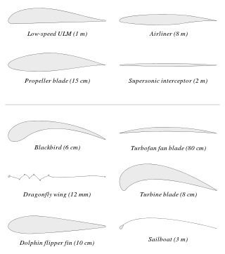
An airfoil or aerofoil is a streamlined body that is capable of generating significantly more lift than drag. Wings, sails and propeller blades are examples of airfoils. Foils of similar function designed with water as the working fluid are called hydrofoils.

Centrifugal compressors, sometimes called impeller compressors or radial compressors, are a sub-class of dynamic axisymmetric work-absorbing turbomachinery.
Blade element theory (BET) is a mathematical process originally designed by William Froude (1878), David W. Taylor (1893) and Stefan Drzewiecki (1885) to determine the behavior of propellers. It involves breaking a blade down into several small parts then determining the forces on each of these small blade elements. These forces are then integrated along the entire blade and over one rotor revolution in order to obtain the forces and moments produced by the entire propeller or rotor. One of the key difficulties lies in modelling the induced velocity on the rotor disk. Because of this the blade element theory is often combined with momentum theory to provide additional relationships necessary to describe the induced velocity on the rotor disk, producing blade element momentum theory. At the most basic level of approximation a uniform induced velocity on the disk is assumed:

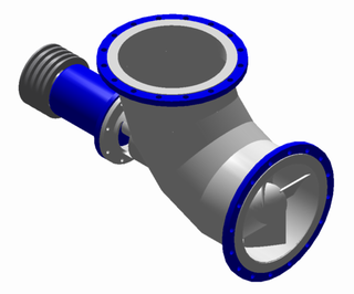
A torque converter is a device, usually implemented as a type of fluid coupling, that transfers rotating power from a prime mover, like an internal combustion engine, to a rotating driven load. In a vehicle with an automatic transmission, the torque converter connects the prime mover to the automatic gear train, which then drives the load. It is thus usually located between the engine's flexplate and the transmission. The equivalent device in a manual transmission is the mechanical clutch.

An axial compressor is a gas compressor that can continuously pressurize gases. It is a rotating, airfoil-based compressor in which the gas or working fluid principally flows parallel to the axis of rotation, or axially. This differs from other rotating compressors such as centrifugal compressor, axi-centrifugal compressors and mixed-flow compressors where the fluid flow will include a "radial component" through the compressor.
An axial-flow pump, or AFP, is a common type of pump that essentially consists of a propeller in a pipe. The propeller can be driven directly by a sealed motor in the pipe or by electric motor or petrol/diesel engines mounted to the pipe from the outside or by a right-angle drive shaft that pierces the pipe.
Specific speedNs, is used to characterize turbomachinery speed. Common commercial and industrial practices use dimensioned versions which are of equal utility. Specific speed is most commonly used in pump applications to define the suction specific speed —a quasi non-dimensional number that categorizes pump impellers as to their type and proportions. In Imperial units it is defined as the speed in revolutions per minute at which a geometrically similar impeller would operate if it were of such a size as to deliver one gallon per minute against one foot of hydraulic head. In metric units flow may be in l/s or m3/s and head in m, and care must be taken to state the units used.
A ratio distribution is a probability distribution constructed as the distribution of the ratio of random variables having two other known distributions. Given two random variables X and Y, the distribution of the random variable Z that is formed as the ratio Z = X/Y is a ratio distribution.

A radial turbine is a turbine in which the flow of the working fluid is radial to the shaft. The difference between axial and radial turbines consists in the way the fluid flows through the components. Whereas for an axial turbine the rotor is 'impacted' by the fluid flow, for a radial turbine, the flow is smoothly orientated perpendicular to the rotation axis, and it drives the turbine in the same way water drives a watermill. The result is less mechanical stress which enables a radial turbine to be simpler, more robust, and more efficient when compared to axial turbines. When it comes to high power ranges the radial turbine is no longer competitive and the efficiency becomes similar to that of the axial turbines.

The primary application of wind turbines is to generate energy using the wind. Hence, the aerodynamics is a very important aspect of wind turbines. Like most machines, wind turbines come in many different types, all of them based on different energy extraction concepts.
In turbomachinery, degree of reaction or reaction ratio is defined as the ratio of the change in static pressure in the rotating blades of a compressor or turbine, to the static pressure change in the compressor or turbine stage. Alternatively it is the ratio of static enthalpy change in the rotor to the static enthalpy change in the stage.
Compressor characteristic is a mathematical curve that shows the behaviour of a fluid going through a dynamic compressor. It shows changes in fluid pressure, temperature, entropy, flow rate etc.) with the compressor operating at different speeds.
Blade element momentum theory is a theory that combines both blade element theory and momentum theory. It is used to calculate the local forces on a propeller or wind-turbine blade. Blade element theory is combined with momentum theory to alleviate some of the difficulties in calculating the induced velocities at the rotor.
In turbomachinery, the slip factor is a measure of the fluid slip in the impeller of a compressor or a turbine, mostly a centrifugal machine. Fluid slip is the deviation in the angle at which the fluid leaves the impeller from the impeller's blade/vane angle. Being quite small in axial impellers, slip is a very important phenomenon in radial impellers and is useful in determining the accurate estimation of work input or the energy transfer between the impeller and the fluid, rise in pressure and the velocity triangles at the impeller exit.
An axial fan is a type of fan that causes gas to flow through it in an axial direction, parallel to the shaft about which the blades rotate. The flow is axial at entry and exit. The fan is designed to produce a pressure difference, and hence force, to cause a flow through the fan. Factors which determine the performance of the fan include the number and shape of the blades. Fans have many applications including in wind tunnels and cooling towers. Design parameters include power, flow rate, pressure rise and efficiency.
In turbomachinery, an axial turbine is a turbine in which the flow of the working fluid is parallel to the shaft, as opposed to radial turbines, where the fluid runs around a shaft, as in a watermill. An axial turbine has a similar construction as an axial compressor, but it operates in the reverse, converting flow of the fluid into rotating mechanical energy.
Three-dimension losses and correlation in turbomachinery refers to the measurement of flow-fields in three dimensions, where measuring the loss of smoothness of flow, and resulting inefficiencies, becomes difficult, unlike two-dimensional losses where mathematical complexity is substantially less.
Rotor solidity is a dimensionless quantity used in design and analysis of rotorcraft, propellers and wind turbines. Rotor solidity is a function of the aspect ratio and number of blades in the rotor and is widely used as a parameter for ensuring geometric similarity in rotorcraft experiments. It provides a measure of how close a lifting rotor system is to an ideal actuator disk in momentum theory. It also plays an important role in determining the fluid speed across the rotor disk when lift is generated and consequentially the performance of the rotor; amount of downwash around it, and noise levels the rotor generates. It is also used to compare performance characteristics between rotors of different sizes. Typical values of rotor solidity ratio for helicopters fall in the range 0.05 to 0.12.
Propeller theory is the science governing the design of efficient propellers. A propeller is the most common propulsor on ships, and on small aircraft.


