Impeller

Last updated
Impeller from a three-stage air compressor Impeller 2.jpg
Impeller from a three-stage air compressor

An impeller, or impellor, [1] is a driven rotor used to increase the pressure and flow of a fluid. It is the opposite of a turbine, which extracts energy from, and reduces the pressure of, a flowing fluid.

Contents

Strictly speaking, propellers are a sub-class of impellers where the flow both enters and leaves axially, but in many contexts the term "impeller" is reserved for non-propeller rotors where the flow enters axially and leaves radially, especially when creating suction in a pump or compressor.

In pumps

Several different types of pump impellers Pump Impellers-1.jpg
Several different types of pump impellers
Flexible impeller of cooling system pump of an outboard engine (Coin for comparison, diameter 16.25 mm) Impellerrad.jpg
Flexible impeller of cooling system pump of an outboard engine (Coin for comparison, diameter 16.25 mm)

An impeller is a rotating component of a centrifugal pump that accelerates fluid outward from the center of rotation, thus transferring energy from the motor that drives the pump to the fluid being pumped. [2] [3] The velocity achieved by the impeller transfers into pressure when the outward movement of the fluid is confined by the pump casing. An impeller is usually a short cylinder with an open inlet (called an eye) to accept incoming fluid, vanes to push the fluid radially, and a splined, keyed, or threaded bore to accept a drive shaft.

It can be cheaper to cast an impeller and its spindle as one piece, rather than separately. This combination is sometimes referred to simply as the "rotor."

Types

Open

An open impeller has a hub with attached vanes and is mounted on a shaft. The vanes do not have a wall, making open impellers slightly weaker than closed or semi-closed impellers. However, as the side plate is not fixed to the inlet side of the vane, the blade stresses are significantly lower. [4] In pumps, the fluid enters the impeller's eye, where vanes add energy and direct it to the nozzle discharge. A close clearance between vanes and pump volute or back plate prevent most of fluid from flowing back. Wear on the bowl and edge of vane can be compensated by adjusting the clearance to maintain efficiency over time. [5] Because the internal parts are visible, open impellers are easier to inspect for damage and maintain than closed impellers. They can also be more easily modified to change flow properties. Open impellers operate on a narrow range of specific speed. Open impellers are usually faster and easier to maintain.  For small pumps and those dealing with suspended solids, open impellers are generally used. [6] Sand locking does not occur as easily as with closed type.

Semi-closed

A semi-closed impeller has an additional back wall, giving it more strength. These impellers can pass mixed solid-liquid mixtures at the cost of reduced efficiency.

Closed or shrouded

The construction of closed impellers includes additional back and front walls on both sides of vanes that enhances its strength. This also reduces the thrust load on the shaft, increasing bearing life and reliability and reducing shafting cost. However, this more complicated design, including the use of additional wear rings, makes closed impellers more difficult to manufacture and more expensive than open impellers. A closed impeller's efficiency decreases as wear ring clearance increases with use. However, adjustment of impeller bowl clearance does not affect the wear on vanes as critically as open impeller. [4] Closed impellers can be used on a wider range specific speed than open impellers. [5] They are generally used in large pumps and clear water applications. These impellers can't perform effectively with solids and become difficult to clean if clogged. [6]

Screw

The screw impeller design aligns more with an axial progressive channel that allows for solids to be openly handled when rotating. [7] [8]

In centrifugal compressors

The main part of a centrifugal compressor is the impeller. An open impeller has no cover, therefore it can work at higher speeds. A compressor with a covered impeller can have more stages than one that has an open impeller.

In water jets

Some impellers are similar to small propellers but without the large blades. Among other uses, they are used in water jets to power high speed boats.

Because impellers do not have large blades to turn, they can spin at much higher speeds than propellers. The water forced through the impeller is channeled by the housing, creating a water jet that propels the vessel forward. The housing is normally tapered into a nozzle to increase the speed of the water, which also creates a Venturi effect in which low pressure behind the impeller pulls more water towards the blades, tending to increase the speed.

To work efficiently, there must be a close fit between the impeller and the housing. The housing is normally fitted with a replaceable wear ring which tends to wear as sand or other particles are thrown against the housing side by the impeller.

Vessels using impellers are normally steered by changing the direction of the water jet.

Compare to propeller and jet aircraft engines.

In agitated tanks

Axial flow impeller (left) and radial flow impeller (right) Mixing - flusso assiale e radiale.jpg
Axial flow impeller (left) and radial flow impeller (right)

Impellers in agitated tanks are used to mix fluids or slurry in the tank. This can be used to combine materials in the form of solids, liquids and gas. Mixing the fluids in a tank is very important if there are gradients in conditions such as temperature or concentration.

There are two types of impellers, depending on the flow regime created (see figure):

Radial flow impellers impose essentially shear stress to the fluid, and are used, for example, to mix immiscible liquids or in general when there is a deformable interface to break. Another application of radial flow impellers is the mixing of very viscous fluids.

Axial flow impellers impose essentially bulk motion and are used on homogenization processes, in which increased fluid volumetric flow rate is important.

Impellers can be further classified principally into three sub-types:

Propellers

Propellers are axial thrust-giving elements. These elements give a very high degree of swirling in the vessel. The flow pattern generated in the fluid resembles a helix.

In washing machines

Agitator for a laundromat washing machine Washing machine agitator.JPG
Agitator for a laundromat washing machine

Some constructions of top loading washing machines use impellers to agitate the laundry during washing.

Firefighting rank badge

Fire services in the United Kingdom and many countries of the Commonwealth use a stylized depiction of an impeller as a rank badge. Officers wear one or more on their epaulettes or the collar of their firefighting uniform as an equivalent to the "pips" worn by the army and police.

In air pumps

Air pumps, such as the roots blower, use meshing impellers to move air through a system. Applications include blast furnaces, ventilation systems, and superchargers for internal combustion engines.

In medicine

Impellers are an integral part of axial-flow pumps, used in ventricular assist devices to augment or fully replace cardiac function. [9] [10]

See also

Related Research Articles

<span class="mw-page-title-main">Pump</span> Device that imparts energy to the fluids by mechanical action

A pump is a device that moves fluids, or sometimes slurries, by mechanical action, typically converted from electrical energy into hydraulic energy.

<span class="mw-page-title-main">Tesla turbine</span> Bladeless centripetal flow turbine

The Tesla turbine is a bladeless centripetal flow turbine invented by Nikola Tesla in 1913. Nozzles apply a moving fluid to the edges of a set of discs. The engine uses smooth discs rotating in a chamber to generate rotational movement due to the exchange of momentum between the fluid and the discs. The discs are arranged in an orientation similar to a stack of CDs on a pole.

<span class="mw-page-title-main">Turbopump</span> Pump driven by a gas turbine

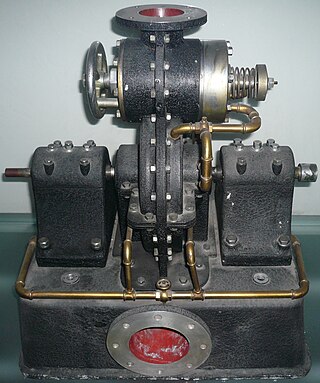
A turbopump is a propellant pump with two main components: a rotodynamic pump and a driving gas turbine, usually both mounted on the same shaft, or sometimes geared together. They were initially developed in Germany in the early 1940s. The purpose of a turbopump is to produce a high-pressure fluid for feeding a combustion chamber or other use. While other use cases exist, they are most commonly found in liquid rocket engines.

<span class="mw-page-title-main">Centrifugal compressor</span> Sub-class of dynamic axisymmetric work-absorbing turbomachinery

Centrifugal compressors, sometimes called impeller compressors or radial compressors, are a sub-class of dynamic axisymmetric work-absorbing turbomachinery.

<span class="mw-page-title-main">Compressor</span> Machine to increase pressure of gas by reducing its volume

A compressor is a mechanical device that increases the pressure of a gas by reducing its volume. An air compressor is a specific type of gas compressor.

<span class="mw-page-title-main">Axial compressor</span> Machine for continuous flow gas compression

An axial compressor is a gas compressor that can continuously pressurize gases. It is a rotating, airfoil-based compressor in which the gas or working fluid principally flows parallel to the axis of rotation, or axially. This differs from other rotating compressors such as centrifugal compressor, axi-centrifugal compressors and mixed-flow compressors where the fluid flow will include a "radial component" through the compressor.

<span class="mw-page-title-main">Turbomachinery</span> Machine for exchanging energy with a fluid

Turbomachinery, in mechanical engineering, describes machines that transfer energy between a rotor and a fluid, including both turbines and compressors. While a turbine transfers energy from a fluid to a rotor, a compressor transfers energy from a rotor to a fluid. It is an important application of fluid mechanics.

<span class="mw-page-title-main">Centrifugal pump</span> Pump used to transport fluids by conversion of rotational kinetic energy

Centrifugal pumps are used to transport fluids by the conversion of rotational kinetic energy to the hydrodynamic energy of the fluid flow. The rotational energy typically comes from an engine or electric motor. They are a sub-class of dynamic axisymmetric work-absorbing turbomachinery. The fluid enters the pump impeller along or near to the rotating axis and is accelerated by the impeller, flowing radially outward into a diffuser or volute chamber (casing), from which it exits.

<span class="mw-page-title-main">Axial-flow pump</span> Type of pump consisting of a propeller in a pipe

An axial-flow pump, or AFP, is a common type of pump that essentially consists of a propeller in a pipe. The propeller can be driven directly by a sealed motor in the pipe or by electric motor or petrol/diesel engines mounted to the pipe from the outside or by a right-angle drive shaft that pierces the pipe.

A compressor map is a chart which shows the performance of a turbomachinery compressor. This type of compressor is used in gas turbine engines, for supercharging reciprocating engines and for industrial processes, where it is known as a dynamic compressor. A map is created from compressor rig test results or predicted by a special computer program. Alternatively the map of a similar compressor can be suitably scaled. This article is an overview of compressor maps and their different applications and also has detailed explanations of maps for a fan and intermediate and high-pressure compressors from a three-shaft aero-engine as specific examples.

A jet engine performs by converting fuel into thrust. How well it performs is an indication of what proportion of its fuel goes to waste. It transfers heat from burning fuel to air passing through the engine. In doing so it produces thrust work when propelling a vehicle but a lot of the fuel is wasted and only appears as heat. Propulsion engineers aim to minimize the degradation of fuel energy into unusable thermal energy. Increased emphasis on performance improvements for commercial airliners came in the 1970s from the rising cost of fuel.

<span class="mw-page-title-main">Gas turbine engine compressors</span> Engine component

As the name suggests, gas turbine engine compressors provide the compression part of the gas turbine engine thermodynamic cycle. There are three basic categories of gas turbine engine compressor: axial compressor, centrifugal compressor and mixed flow compressor. A fourth, unusual, type is the free-piston gas generator, which combines the functions of compressor and combustion chamber in one unit.

<span class="mw-page-title-main">Centrifugal fan</span> Mechanical fan that forces fluid to move radially outward

A centrifugal fan is a mechanical device for moving air or other gases in a direction at an angle to the incoming fluid. Centrifugal fans often contain a ducted housing to direct outgoing air in a specific direction or across a heat sink; such a fan is also called a blower, blower fan, or squirrel-cage fan. Tiny ones used in computers are sometimes called biscuit blowers. These fans move air from the rotating inlet of the fan to an outlet. They are typically used in ducted applications to either draw air through ductwork/heat exchanger, or push air through similar impellers. Compared to standard axial fans, they can provide similar air movement from a smaller fan package, and overcome higher resistance in air streams.

<span class="mw-page-title-main">Fan (machine)</span> Machine used to produce air flow

A fan is a powered machine used to create a flow of air. A fan consists of a rotating arrangement of vanes or blades, generally made of wood, plastic, or metal, which act on the air. The rotating assembly of blades and hub is known as an impeller, rotor, or runner. Usually, it is contained within some form of housing, or case. This may direct the airflow, or increase safety by preventing objects from contacting the fan blades. Most fans are powered by electric motors, but other sources of power may be used, including hydraulic motors, handcranks, and internal combustion engines.

Industrial fans and blowers are machines whose primary function is to provide and accommodate a large flow of air or gas to various parts of a building or other structures. This is achieved by rotating a number of blades, connected to a hub and shaft, and driven by a motor or turbine. The flow rates of these mechanical fans range from approximately 200 cubic feet (5.7 m3) to 2,000,000 cubic feet (57,000 m3) per minute. A blower is another name for a fan that operates where the resistance to the flow is primarily on the downstream side of the fan.

A rotodynamic pump is a kinetic machine in which energy is continuously imparted to the pumped fluid by means of a rotating impeller, propeller, or rotor, in contrast to a positive-displacement pump in which a fluid is moved by trapping a fixed amount of fluid and forcing the trapped volume into the pump's discharge. Examples of rotodynamic pumps include adding kinetic energy to a fluid such as by using a centrifugal pump to increase fluid velocity or pressure.

Industrial agitators are machines used to stir or mix fluids in industries that process products in the chemical, food, pharmaceutical and cosmetic industries. Their uses include:

An axial turbine is a turbine in which the flow of the working fluid is parallel to the shaft, as opposed to radial turbines, where the fluid runs around a shaft, as in a watermill. An axial turbine has a similar construction as an axial compressor, but it operates in the reverse, converting flow of the fluid into rotating mechanical energy.

Three-dimension losses and correlation in turbomachinery refers to the measurement of flow-fields in three dimensions, where measuring the loss of smoothness of flow, and resulting inefficiencies, becomes difficult, unlike two-dimensional losses where mathematical complexity is substantially less.

Radial means that the fluid is flowing in radial direction that is either from inward to outward or from outward to inward. If the fluid is flowing from inward to outward then it is called outflow radial turbine.

  1. In such turbines, the water enters at the centre of the wheel and then flows outwards.
  2. Here guide mechanism is surrounded by the runner.
  3. In this turbine, the inner diameter of the runner is the inlet and outer diameter is an outlet.

References

  1. "impeller, n.". OED Online. March 2013. Oxford University Press. 20 March 2013 .
  2. Gülich, Johann Friedrich (2010). Centrifugal Pumps (2nd ed.). ISBN   978-3-642-12823-3.
  3. Manuals, Seloc Marine (2008). Volvo Penta Stern Drives 2003-2012: Gasoline Engines & Drive Systems (Seloc Marine Manuals. Seloc Publishing. ISBN   978-0893300746.
  4. 1 2 "Pump Design and Characteristic". The New Zealand Digital Library.
  5. 1 2 "Open vs. closed impellers – Mc Nally Institute". mcnallyinstitute.
  6. 1 2 "Open and Closed Impellers". Turbomachineary International.
  7. "Types of Impeller in Pumps - Selections and Considerations". 30 January 2021.
  8. Lin, Peng; Liu, Meiqing; Zhao, Wensheng; Liu, Zhiyong; Wu, Yuanwei; Xue, Fei; Zhang, Yipeng (2017). "Influence of tip clearance on the performance of a screw axial-flow pump". Advances in Mechanical Engineering. 9 (6). doi: 10.1177/1687814017704357 . S2CID   117627953.
  9. Miller, LW; Pagani, FD (2007). "Use of a continuous-flow device in patients awaiting heart transplantation". N Engl J Med. 357 (9): 885–96. doi: 10.1056/nejmoa067758 . PMID   17761592.
  10. Chou, N. K.; Wang, S. S.; Chu, S. H.; Chen, Y. S.; Lin, Y. H.; Chang, C. J.; Shyu, J. J.; Jan, G. J. (2001). "Physiologic analysis of cardiac cycle in an implantable impeller centrifugal left ventricular assist device". Artificial Organs. 25 (8): 613–6. doi:10.1046/j.1525-1594.2001.025008613.x. PMID   11531711.