
A coupling is a device used to connect two shafts together at their ends for the purpose of transmitting power. The primary purpose of couplings is to join two pieces of rotating equipment while permitting some degree of misalignment or end movement or both. In a more general context, a coupling can also be a mechanical device that serves to connect the ends of adjacent parts or objects. Couplings do not normally allow disconnection of shafts during operation, however there are torque-limiting couplings which can slip or disconnect when some torque limit is exceeded. Selection, installation and maintenance of couplings can lead to reduced maintenance time and maintenance cost.
A gear is a rotating circular machine part having cut teeth or, in the case of a cogwheel or gearwheel, inserted teeth, which mesh with another (compatible) toothed part to transmit (convert) torque and speed. The basic principle behind the operation of gears is analogous to the basic principle of levers. A gear may also be known informally as a cog. Geared devices can change the speed, torque, and direction of a power source. Gears of different sizes produce a change in torque, creating a mechanical advantage, through their gear ratio, and thus may be considered a simple machine. The rotational speeds, and the torques, of two meshing gears differ in proportion to their diameters. The teeth on the two meshing gears all have the same shape.
A rack and pinion is a type of linear actuator that comprises a circular gear engaging a linear gear. Together, they convert rotational motion into linear motion. Rotating the pinion causes the rack to be driven in a line. Conversely, moving the rack linearly will cause the pinion to rotate. A rack and pinion drive can use both straight and helical gears. Though some suggest helical gears are quieter in operation, no hard evidence supports this theory. Helical racks, while being more affordable, have proven to increase side torque on the datums, increasing operating temperature leading to premature wear. Straight racks require a lower driving force and offer increased torque and speed per percentage of gear ratio which allows lower operating temperature and lessens viscal friction and energy use. The maximum force that can be transmitted in a rack and pinion mechanism is determined by the tooth pitch and the size of the pinion as well as the gear ratio.

Hobbing is a machining process for gear cutting, cutting splines, and cutting sprockets using a hobbing machine, a specialized milling machine. The teeth or splines of the gear are progressively cut into the material by a series of cuts made by a cutting tool called a hob.
A power take-off or power takeoff (PTO) is one of several methods for taking power from a power source, such as a running engine, and transmitting it to an application such as an attached implement or separate machine.

In automotive design, a front-engine, front-wheel-drive (FWD) layout, or FF layout, places both the internal combustion engine and driven roadwheels at the front of the vehicle.
A constant-velocity joint is a mechanical coupling which allows the shafts to rotate freely as the angle between the two shafts moves within a certain range.

A drive shaft, driveshaft, driving shaft, tailshaft, propeller shaft, or Cardan shaft is a component for transmitting mechanical power and torque and rotation, usually used to connect other components of a drivetrain that cannot be connected directly because of distance or the need to allow for relative movement between them.

A gear train is a machine element of a mechanical system formed by mounting gears on a frame so the teeth of the gears engage.

On a bicycle, the cassette or cluster is the set of multiple sprockets that attaches to the hub on the rear wheel. A cogset works with a rear derailleur to provide multiple gear ratios to the rider. Cassettes come in two varieties, freewheels or cassettes, of which cassettes are a newer development. Although cassettes and freewheels perform the same function and look almost the same when installed, they have important mechanical differences and are not interchangeable.
A cycloidal drive or cycloidal speed reducer is a mechanism for reducing the speed of an input shaft by a certain ratio. Cycloidal speed reducers are capable of relatively high ratios in compact sizes with very low backlash.

Bevel gears are gears where the axes of the two shafts intersect and the tooth-bearing faces of the gears themselves are conically shaped. Bevel gears are most often mounted on shafts that are 90 degrees apart, but can be designed to work at other angles as well. The pitch surface of bevel gears is a cone, known as a pitch cone. Bevel gears transfer the energy from linear to vertical power, making it very useful in machines widely used in mechanical settings.
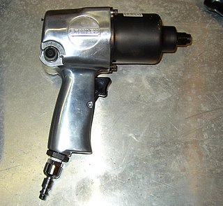
An impact wrench is a socket wrench power tool designed to deliver high torque output with minimal exertion by the user, by storing energy in a rotating mass, then delivering it suddenly to the output shaft. It was invented by Robert H. Pott of Evansville, Indiana.
Gear cutting is any machining process for creating a gear. The most common gear-cutting processes include hobbing, broaching, milling, grinding, and skiving. Such cutting operations may occur either after or instead of forming processes such as forging, extruding, investment casting, or sand casting.
Vehicles made by American Motors Corporation (AMC) and Jeep incorporated a variety of transmissions and transfer case systems. This article covers transmissions used in the following vehicle models and years:

A Hirth joint or Hirth coupling is a type of mechanical connection named after its developer Albert Hirth. It is used to connect two pieces of a shaft together and is characterized by tapered teeth that mesh together on the end faces of each half shaft.
In mechanical engineering, a key is a machine element used to connect a rotating machine element to a shaft. The key prevents relative rotation between the two parts and may enable torque transmission. For a key to function, the shaft and rotating machine element must have a keyway and a keyseat, which is a slot and pocket in which the key fits. The whole system is called a keyed joint. A keyed joint may allow relative axial movement between the parts.

In engineering, a mechanism is a device that transforms input forces and movement into a desired set of output forces and movement. Mechanisms generally consist of moving components which may include:

A torque multiplier is a tool used to provide a mechanical advantage in applying torque to turn bolts, nuts or other items designed to be actuated by application of torque, particularly where there are relatively high torque requirements.

Strain wave gearing is a type of mechanical gear system that uses a flexible spline with external teeth, which is deformed by a rotating elliptical plug to engage with the internal gear teeth of an outer spline.
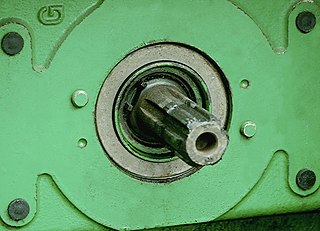
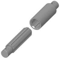 Detail of a spline joint
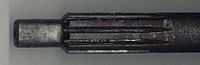 A spline on the end of a manual transmission input shaft
 Clutch disc with splined hub to mesh with pictured input shaft
 A drive shaft with a spline in the center and universal joints at the ends to transmit torque and rotation and allow for changes in length
 Splines on the CV end of an axle shaft
 Matching splines of a bicycle cassette and freehub with a master spline visible at the top


