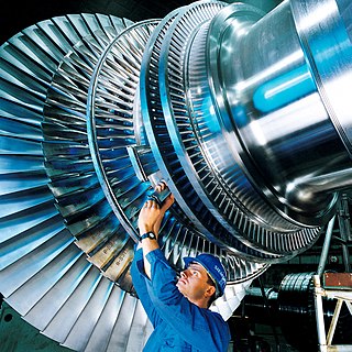
Axial fan design

Last updated

An axial fan is a type of fan that causes gas to flow through it in an axial direction, parallel to the shaft about which the blades rotate. The flow is axial at entry and exit. The fan is designed to produce a pressure difference, and hence force, to cause a flow through the fan. Factors which determine the performance of the fan include the number and shape of the blades. Fans have many applications including in wind tunnels and cooling towers. Design parameters include power, flow rate, pressure rise and efficiency. [1]

Contents

Axial fans generally comprise fewer blades (two to six) than centrifugal fans. Axial fans commonly have larger radius and lower speed (ω) than ducted fans (esp. at similar power. Stress proportional to r^2).

Calculation of parameters

Since the calculation cannot be done using the inlet and outlet velocity triangles, which is not the case in other turbomachines, calculation is done by considering a mean velocity triangle for flow only through an infinitesimal blade element. The blade is divided into many small elements and various parameters are determined separately for each element. [1] There are two theories that solve the parameters for axial fans: [1]

Slipstream theory

Variation of Pressure and Velocity of Flow through a Propeller disc. Axial fan slipstream theory.svg
Variation of Pressure and Velocity of Flow through a Propeller disc.

In the figure, the thickness of the propeller disc is assumed to be negligible. The boundary between the fluid in motion and fluid at rest is shown. Therefore, the flow is assumed to be taking place in an imaginary converging duct [1] [2] where:

Parameters at −∞ and +∞ and their relationship
Parameter Pressure Density Velocity Stagnation enthalpy Static Enthalpy
−∞PaρaCu (upstream velocity)houhu
+∞PaρaCs (slipstream velocity)hodhd
RelationshipEqualEqualUnequalUnequalEqual
CommentsPressure will be atmospheric at both −∞ and +∞Density will be equal at both −∞ and +∞Velocity will change due to flow across an assumed converging ductStagnation enthalpy will be different at −∞ and +∞The static Enthalpy will be same at −∞ and +∞ as it depends upon the atmospheric conditions that will be the same

In the figure, across the propeller disc, velocities (C1 and C2) cannot change abruptly across the propeller disc as that will create a shockwave but the fan creates the pressure difference across the propeller disc. [1]

and

On subtracting the above equations: [1]

Comparing this thrust with the axial thrust due to change in momentum of air flow, it is found that: [1]

A parameter 'a' is defined such that [1] -

where

Using the previous equation and "a", an expression for Cs comes out to be:

Now, Ideal Value of Power supplied to the Propeller = Mass flow rate * Change in Stagnation enthalpy; [1]

where

If propeller was employed to propel an aircraft at speed = Cu; then Useful Power = Axial Thrust * Speed of Aircraft; [1]

Therefore;

Hence the flow can be modeled where the air flows through an imaginary diverging duct, where diameter of propeller disc and diameter of the outlet are related. [1]

Blade element theory

Long Blade of a Propeller Fan with varying Blade Section. BLADE DESIGN.jpg
Long Blade of a Propeller Fan with varying Blade Section.

In this theory, a small element (dr) is taken at a distance r from the root of the blade and all the forces acting on the element are analysed to get a solution. It is assumed that the flow through each section of small radial thickness dr is assumed to be independent of the flow through other elements. [1] [3]

The figure shows the Velocities and Blade Forces for the Flow across the element dr, where w is the Mean Velocity at a direction b from Axial direction. DL = Lift Force (Perpendicular to w) and DD = Drag Force (Parallel to 'w'). The Axial and Tangential forces are DFx and DFy respectively and the Resultant force DFr is at an angle Ph to the Lift. Blade Forces.jpg
The figure shows the Velocities and Blade Forces for the Flow across the element dr, where w is the Mean Velocity at a direction β from Axial direction. ΔL = Lift Force (Perpendicular to w) and ΔD = Drag Force (Parallel to 'w'). The Axial and Tangential forces are ΔFx and ΔFy respectively and the Resultant force ΔFr is at an angle Φ to the Lift.

Resolving Forces in the figure [1] -

Lift Coefficient (CL) and Drag Coefficient (CD) are given as -

Also from the figure [1] -

Now,

No. of Blades (z) and Spacing (s) are related as, [1] and the total thrust for the elemental section of the propeller is zΔFx.

Therefore, [1]

Similarly, solving for ΔFy, ΔFy is found out to be [1] -

and

Finally, thrust and torque can be found out for an elemental section as they are proportional to Fx and Fy respectively. [1]

Performance characteristics

This Figure shows the Performance Curve for Axial Flow Fan. PERFORMANCE CURVE.jpg
This Figure shows the Performance Curve for Axial Flow Fan.

The relationship between the pressure variation and the volume flow rate are important characteristics of fans. The typical characteristics of axial fans can be studied from the performance curves. The performance curve for the axial fan is shown in the figure. (The vertical line joining the maximum efficiency point is drawn which meets the Pressure curve at point "S") [1] The following can be inferred from the curve -

  1. As the flow rate increases from zero the efficiency increases to a particular point reaches maximum value and then decreases.
  2. The power output of the fans increases with almost constant positive slope.
  3. The pressure fluctuations are observed at low discharges and at flow rates(as indicated by the point "S" ) the pressure deceases.
  4. The pressure variations to the left of the point "S" causes for unsteady flow which are due to the two effects of Stalling and surging.

Causes of unstable flow

Stalling and surging affects the fan performance, blades, as well as output and are thus undesirable. They occur because of the improper design, fan physical properties and are generally accompanied by noise generation.

Stalling effect/Stall

The cause for this is the separation of the flow from the blade surfaces. This effect can be explained by the flow over an air foil. When the angle of incidence increases (during the low velocity flow) at the entrance of the air foil, flow pattern changes and separation occurs. This is the first stage of stalling and through this separation point the flow separates leading to the formation of vortices, back flow in the separated region. For a further the explanation of stall and rotating stall, refer to compressor surge. The stall zone for the single axial fan and axial fans operated in parallel are shown in the figure. [4]

The Figure shows the Stall Prone Areas differently for One fan and Two fans in parallel. Stall Areas.jpg
The Figure shows the Stall Prone Areas differently for One fan and Two fans in parallel.

The following can be inferred from the graph :

VFDs are not practical for some Axial fans

Many Axial fan failures have happened after controlled blade axial fans were locked in a fixed position and Variable Frequency Drives (VFDs) were installed. The VFDs are not practical for some Axial fans. Axial fans with severe instability regions should not be operated at blades angles, rotational speeds, mass flow rates, and pressures that expose the fan to stall conditions. [5]

Surging effect/Surge

Surging should not be confused with stalling. Stalling occurs only if there is insufficient air entering into the fan blades causing separation of flow on the blade surface. Surging or the Unstable flow causing complete breakdown in fans is mainly contributed by the three factors

System surge

This situation occurs when the system resistance curve and static pressure curve of the fan intersect have similar slope or parallel to each other. Rather than intersecting at a definite point the curves intersect over certain region reporting system surge. These characteristics are not observed in axial fans.

Fan surge

This unstable operation results from the development of pressure gradients in the opposite direction of the flow. Maximum pressure is observed at the discharge of the impeller blade and minimum pressure on the side opposite to the discharge side. When the impeller blades are not rotating these adverse pressure gradients pump the flow in the direction opposite to the direction of the fan. The result is the oscillation of the fan blades creating vibrations and hence noise. [6]

Paralleling

This effect is seen only in case of multiple fans. The air flow capacities of the fans are compared and connected in same outlet or same inlet conditions. This causes noise, specifically referred to as Beating in case of fans in parallel. To avoid beating use is made of differing inlet conditions, differences in rotational speeds of the fans, etc.

Methods to avoid unsteady flow

By designing the fan blades with proper hub-to-tip ratio and analyzing performance on the number of blades so that the flow doesn't separate on the blade surface these effects can be reduced. Some of the methods to overcome these effects are re-circulation of excess air through the fan, axial fans are high specific speed devices operating them at high efficiency and to minimize the effects they have to be operated at low speeds. For controlling and directing the flow use of guide vanes is suggested. Turbulent flows at the inlet and outlet of the fans cause stalling so the flow should be made laminar by the introduction of a stator to prevent the effect. [7]

See also

Notes

  1. 1 2 3 4 5 6 7 8 9 10 11 12 13 14 15 16 17 18 19 20 21 22 23 24 25 26 Yahya, S. M. (2010). "Ch. 14". Turbines Compressors And Fans (4th ed.). McGraw-Hill. pp. 622–9. ISBN   978-0-07-070702-3.
  2. POOLE, R (1 Jan 1935). "The Theory and Design of Propeller-Type Fans". Selected Engineering Papers. 1 (178). doi:10.1680/isenp.1935.13442.
  3. Marble, Frank E. (1948). "The Flow of a Perfect Fluid Through an Axial Turbomachine with Prescribed Blade Loading". Journal of the Aeronautical Sciences. Institute of the Aeronautical Sciences. 15 (8): 473–485. doi:10.2514/8.11624.
  4. 1 2 "Stall, Problems and Solutions" (PDF). Archived from the original (PDF) on 2013-10-03. Retrieved 2013-05-10.
  5. "Improving Fan System Performance" (PDF). U.S. Dept. of Energy. p. 35 (39/92), Last paragraph.
  6. "System Surge, Fan Surge and Paralleling" (PDF). Archived from the original (PDF) on 2007-01-13. Retrieved 2013-05-12.
  7. "Destratification Fans by Airius". Airius LLC. Archived from the original on 20 April 2017. Retrieved 19 April 2017.

Related Research Articles

<span class="mw-page-title-main">Centripetal force</span> Force directed to the center of rotation

A centripetal force is a force that makes a body follow a curved path. The direction of the centripetal force is always orthogonal to the motion of the body and towards the fixed point of the instantaneous center of curvature of the path. Isaac Newton described it as "a force by which bodies are drawn or impelled, or in any way tend, towards a point as to a centre". In the theory of Newtonian mechanics, gravity provides the centripetal force causing astronomical orbits.

<span class="mw-page-title-main">Steam turbine</span> Machine that uses steam to rotate a shaft

A steam turbine is a machine that extracts thermal energy from pressurized steam and uses it to do mechanical work on a rotating output shaft. Its modern manifestation was invented by Charles Parsons in 1884. Fabrication of a modern steam turbine involves advanced metalwork to form high-grade steel alloys into precision parts using technologies that first became available in the 20th century; continued advances in durability and efficiency of steam turbines remains central to the energy economics of the 21st century.

<span class="mw-page-title-main">Laplace's equation</span> Second-order partial differential equation

In mathematics and physics, Laplace's equation is a second-order partial differential equation named after Pierre-Simon Laplace, who first studied its properties. This is often written as

<span class="mw-page-title-main">Navier–Stokes equations</span> Equations describing the motion of viscous fluid substances

The Navier–Stokes equations are partial differential equations which describe the motion of viscous fluid substances. They were named after French engineer and physicist Claude-Louis Navier and the Irish physicist and mathematician George Gabriel Stokes. They were developed over several decades of progressively building the theories, from 1822 (Navier) to 1842–1850 (Stokes).

In fluid mechanics, the Grashof number is a dimensionless number which approximates the ratio of the buoyancy to viscous forces acting on a fluid. It frequently arises in the study of situations involving natural convection and is analogous to the Reynolds number.

Blade element theory (BET) is a mathematical process originally designed by William Froude (1878), David W. Taylor (1893) and Stefan Drzewiecki (1885) to determine the behavior of propellers. It involves breaking a blade down into several small parts then determining the forces on each of these small blade elements. These forces are then integrated along the entire blade and over one rotor revolution in order to obtain the forces and moments produced by the entire propeller or rotor. One of the key difficulties lies in modelling the induced velocity on the rotor disk. Because of this the blade element theory is often combined with momentum theory to provide additional relationships necessary to describe the induced velocity on the rotor disk, producing blade element momentum theory. At the most basic level of approximation a uniform induced velocity on the disk is assumed:

<span class="mw-page-title-main">Fermi's interaction</span> Mechanism of beta decay proposed in 1933

In particle physics, Fermi's interaction is an explanation of the beta decay, proposed by Enrico Fermi in 1933. The theory posits four fermions directly interacting with one another. This interaction explains beta decay of a neutron by direct coupling of a neutron with an electron, a neutrino and a proton.

In physics, the Hamilton–Jacobi equation, named after William Rowan Hamilton and Carl Gustav Jacob Jacobi, is an alternative formulation of classical mechanics, equivalent to other formulations such as Newton's laws of motion, Lagrangian mechanics and Hamiltonian mechanics.

The Kerr–Newman metric is the most general asymptotically flat, stationary solution of the Einstein–Maxwell equations in general relativity that describes the spacetime geometry in the region surrounding an electrically charged, rotating mass. It generalizes the Kerr metric by taking into account the field energy of an electromagnetic field, in addition to describing rotation. It is one of a large number of various different electrovacuum solutions, that is, of solutions to the Einstein–Maxwell equations which account for the field energy of an electromagnetic field. Such solutions do not include any electric charges other than that associated with the gravitational field, and are thus termed vacuum solutions.

In the mathematical description of general relativity, the Boyer–Lindquist coordinates are a generalization of the coordinates used for the metric of a Schwarzschild black hole that can be used to express the metric of a Kerr black hole.

<span class="mw-page-title-main">Multiple integral</span> Generalization of definite integrals to functions of multiple variables

In mathematics (specifically multivariable calculus), a multiple integral is a definite integral of a function of several real variables, for instance, f(x, y) or f(x, y, z). Physical (natural philosophy) interpretation: S any surface, V any volume, etc.. Incl. variable to time, position, etc.

The Kutta–Joukowski theorem is a fundamental theorem in aerodynamics used for the calculation of lift of an airfoil translating in a uniform fluid at a constant speed large enough so that the flow seen in the body-fixed frame is steady and unseparated. The theorem relates the lift generated by an airfoil to the speed of the airfoil through the fluid, the density of the fluid and the circulation around the airfoil. The circulation is defined as the line integral around a closed loop enclosing the airfoil of the component of the velocity of the fluid tangent to the loop. It is named after Martin Kutta and Nikolai Zhukovsky who first developed its key ideas in the early 20th century. Kutta–Joukowski theorem is an inviscid theory, but it is a good approximation for real viscous flow in typical aerodynamic applications.

In mathematics, vector spherical harmonics (VSH) are an extension of the scalar spherical harmonics for use with vector fields. The components of the VSH are complex-valued functions expressed in the spherical coordinate basis vectors.

Acoustic streaming is a steady flow in a fluid driven by the absorption of high amplitude acoustic oscillations. This phenomenon can be observed near sound emitters, or in the standing waves within a Kundt's tube. Acoustic streaming was explained first by Lord Rayleigh in 1884. It is the less-known opposite of sound generation by a flow.

In nonideal fluid dynamics, the Hagen–Poiseuille equation, also known as the Hagen–Poiseuille law, Poiseuille law or Poiseuille equation, is a physical law that gives the pressure drop in an incompressible and Newtonian fluid in laminar flow flowing through a long cylindrical pipe of constant cross section. It can be successfully applied to air flow in lung alveoli, or the flow through a drinking straw or through a hypodermic needle. It was experimentally derived independently by Jean Léonard Marie Poiseuille in 1838 and Gotthilf Heinrich Ludwig Hagen, and published by Poiseuille in 1840–41 and 1846. The theoretical justification of the Poiseuille law was given by George Stokes in 1845.

Blade element momentum theory is a theory that combines both blade element theory and momentum theory. It is used to calculate the local forces on a propeller or wind-turbine blade. Blade element theory is combined with momentum theory to alleviate some of the difficulties in calculating the induced velocities at the rotor.

<span class="mw-page-title-main">Blade solidity</span>

Blade solidity is an important design parameter for the axial flow impeller and is defined as the ratio of blade chord length to spacing.

Flotation of flexible objects is a phenomenon in which the bending of a flexible material allows an object to displace a greater amount of fluid than if it were completely rigid. This ability to displace more fluid translates directly into an ability to support greater loads, giving the flexible structure an advantage over a similarly rigid one. Inspiration to study the effects of elasticity are taken from nature, where plants, such as black pepper, and animals living at the water surface have evolved to take advantage of the load-bearing benefits elasticity imparts.

Propeller theory is the science governing the design of efficient propellers. A propeller is the most common propulsor on ships, and on small aircraft.

The Izbash formula is a mathematical expression used to calculate the stability of armourstone in flowing water environments.

References