Industrial fan

Last updated

Industrial fans and blowers are machines whose primary function is to provide and accommodate a large flow of air or gas to various parts of a building or other structures. This is achieved by rotating a number of blades, connected to a hub and shaft, and driven by a motor or turbine. The flow rates of these mechanical fans range from approximately 200 cubic feet (5.7 m3) to 2,000,000 cubic feet (57,000 m3) per minute. A blower is another name for a fan that operates where the resistance to the flow is primarily on the downstream side of the fan.

Contents

Functions and industries

There are many uses for the continuous flow of air or gas that industrial fans generate, including combustion, ventilation, aeration, particulate transport, exhaust, cooling, air-cleaning, and drying, to name a few. The industries served include electrical power production, pollution control, metal manufacturing and processing, cement production, mining, petrochemical, food processing, cryogenics, and clean rooms.

Centrifugal fans and axial fans

Most industrial fans may be categorized into one of two general types: centrifugal fans and axial fans.

Centrifugal

The centrifugal design uses the centrifugal force generated by a rotating disk, with blades mounted at right angles to the disk, to impart movement to the air or gas and increase its pressure. The assembly of the hub, disk and blades is known as the fan wheel, and often includes other components with aerodynamic or structural functions. The centrifugal fan wheel is typically contained within a scroll-shaped fan housing, resembling the shell of the nautilus sea creature with a central hole. The air or gas inside the spinning fan is thrown off the outside of the wheel, to an outlet at the housing's largest diameter. This simultaneously draws more air or gas into the wheel through the central hole. [1] Inlet and outlet ducting are often attached to the fan's housing, to supply and/or exhaust the air or gas to the industry's requirements.

There are many varieties of centrifugal fans, which may have fan wheels that range from less than 3 cm to over 16 feet (4.9 m) in diameter.

Axial

The axial design uses axial forces to achieve the movement of the air or gas, spinning a central hub with blades extending radially from its outer diameter. The fluid is moved parallel to the fan wheel's shaft, or axis of rotation. The axial fan is often contained within a short section of cylindrical ductwork, to which inlet and outlet ducting can be connected.

Axial fan types have fan wheels with diameters that usually range from less than a foot (0.3 meters) to over 30 feet (9.1 m), although axial cooling tower fan wheels may exceed 82 feet (25 m) in diameter.

In general, axial fans are used where the principal requirement is for a large volume of flow, and the centrifugal design where both flow and higher pressures are required. Axial fans provide huge airflow at low pressures. They draw air parallel to the axis and force it straight out.

Design paths

There are several paths to determining a fan design for an application.

For industries where the application requirements do not vary greatly and applicable fan designs have diameters of around 4 feet (1.2 meters) or less, a standard or pre-engineered design might be selected.

When the application involves more complex specifications or a larger fan, then a design based on an existing model configuration will often satisfy the requirements. Many model configurations already cover the range of current industry processes. An appropriate model from the fan company's catalogue is selected, and the company's engineers apply design rules to calculate the dimensions and select options and material for the desired performance, strength and operating environment.

Some applications require a dedicated, custom configuration for a fan design to satisfy all specifications.

All industrial fan designs must be accurately engineered to meet performance specifications while maintaining structural integrity. For each application, there are specific flow and pressure requirements. Depending on the application, the fan may be subject to high rotating speeds, an operating environment with corrosive chemicals or abrasive air streams, and extreme temperatures. Larger fans and higher speeds produce greater forces on the rotating structures; for safety and reliability, the design must eliminate excessive stresses and excitable resonant frequencies. Computer modeling programs for computational fluid dynamics (CFD) and finite element analysis (FEA) are often employed in the design process, in addition to laboratory scale model testing. Even after the fan is built the verification might continue, using fan performance testing for flow and pressure, strain gage testing for stresses and tests to record the fan's resonant frequencies.

Fan subtypes

Fan types and their subtypes are industry standard, recognized by all major fan producers. [2]

Centrifugal

Any of these fan subtypes can be built with long-lasting erosion-resistant liners.

Airfoil (Air foil) – Used for a wide range of applications in many industries, fans with hollow, airfoil-profiled blades are designed for use in airstreams where high efficiency and quiet operation are required. They are used extensively for continuous service at ambient and elevated temperatures in forced and induced draft applications in the metals, chemical, power generation, paper, rock products, glass, resource recovery, incineration and other industries throughout the world.

Backward curve – These fans have efficiencies nearly as high as the airfoil design. An advantage is that their single-thickness, curved plate blades prevent the possibility of dust particle buildup inside the blade, as may occur with perforated airfoil blades. The robust design allows high tip-speed operation, and therefore this fan is often used in high-pressure applications.

Backward inclined – These fans have simple flat blades, backwardly inclined to match the velocity pattern of the air passing through the fan wheel for high-efficiency operation. These fans are typically used in high-volume, relatively low-pressure, clean air applications.

Radial blade – The flat blades of this type are arranged in a radial pattern. These rugged fans offer high pressure capability with average efficiency. They are often fitted with erosion-resistant liners to extend rotor life. The housing design is compact to minimize the floor space requirement.

Radial tipped – These fans have wheels that are backward curved, but in a way slightly different from backward curved fans. Backward curved fans have wheels whose blades curve outward, while radial-tip fans' blades are curved inward and radial at their tips (hence the name "radial tip"), while still in a backwardly-curved configuration. Their curvature can also be thought of as radial at the tips but gradually sloping toward the direction of rotation. This rugged design is used in high-volume flow rate applications when the pressure requirement is rather high and erosion resistance is necessary. It offers medium efficiencies. A common application is the dirty side of a baghouse or precipitator. The design is more compact than airfoil, backward curved or backward inclined fans.

Paddle-wheel – This is an open impeller design without shrouds. Although the efficiency is not high, this fan is well suited for applications with extremely high dust loading. It can be offered with field-replaceable blade liners from ceramic tiles or tungsten carbide. This fan may also be used in high-temperature applications.

Forward-curve – This "squirrel cage" impeller generates the highest volume flow rate (for a given tip speed) of all the centrifugal fans. Therefore, it often has the advantage of offering the smallest physical package available for a given application. This type of fan is commonly used in high-temperature furnaces. However, these fans can only be used for conveying air with low dust loading because they are the most sensitive to particle build-up, but also due to the large number of blades that forward-curve wheels require.

Industrial exhausters – This is a relatively inexpensive, medium-duty, steeply inclined flat-bladed fan for exhausting gases, conveying chips, etc.

Pre-engineered fans (PE) – A series of fans of varying blade shapes that are usually available in only standard sizes. Because they are pre-engineered these fans may be available with relatively short delivery times. Often, pre-engineered rotors with various blade shapes may be installed into a common housing. These are often available in a wide range of volume and pressure requirements to meet the needs of many applications.

Pressure blowers – These are high-pressure, low-volume blowers used in combustion air applications in furnaces or to provide “blow-off” air for clearing and/or drying applications.

Surgeless blowers – These high-pressure, low-volume blowers have a reduced tendency for “surging” (periodic variation of flow rate) even at severely reduced fan speeds. This allows extreme turndown (low-flow) without significant pulsation.

Mechanical vapor recovery blowers -These specially designed centrifugal fans are designed to increase temperature and pressure of saturated steam in a closed-loop system.

Acid gas blowers - These very heavy construction blowers are suitable for inlet pressures from full vacuum to 100 psig. Materials are selected for corrosion resistance to the gases and particulate handled.

Specialty process gas blowers - These blowers are for high pressure petrochemical processes.

Axial

High-temperature axial fans – These are high-volume fans designed to operate against low flow resistance in industrial convection furnaces. They may be of either single-direction or bi-directional designs. Extremely rugged, they are most often used in high-temperature furnace (up to 1800 degF) application.

Tube axial fans – These are axial fan units with fan wheels located in cylindrical tubes, without inlet or outlet dampers.

Vaneaxial fans – These axial flow fans have a higher pressure capability due to the presence of static vanes.

Variable pitch axial fans – The blades on these axial fans are manually adjustable to permit the blade angle to be changed. This allows operation over a much wider range of volume/pressure relationships. The blades are adjusted periodically to optimize efficiency by matching the blade pitch to the varying conditions for the application. These fans are often used in mining applications.

Variable pitch on-the-fly axial fans – These are similar to “Variable Pitch Axial Fans” except they include an internal mechanism that allows the blade pitch to be adjusted while the fan rotor is in motion. These versatile fans offer high-efficiency operation at many different points of operation. This instantaneous blade adjustment capability is an advantage that is possible with axial fans only.

Cooling fans - (also referred to as "cooling tower fans") - These are axial fans, typically with large diameters, for low pressures and large volumes of airflow. Applications are in wet mechanical cooling towers, air-cooled steam condensers, air-cooled heat exchangers, radiators, or similar air-cooled applications.

Mixed-flow fans - The gas flow patterns these fans produce resemble a combination of axial and centrifugal patterns, although the fan wheels often appear similar to centrifugal wheels. There are various types of mixed-flow fans, including gas-tight high-pressure fans and blowers.

Jet

Jet Fans are used for daily ventilation requirements and smoke extraction in case of fire (250 ® C/120 min) These Industrial fans have symmetrical impeller blades; 100% reversible with low noise emissions IP55 motors, insulation class H (smoke extraction version). Application for Basement Ventilation & Tunnel Ventilation etc.

Flow control

There are several means of controlling the flow rate of a fan, e.g., temporarily reducing the air or gas flow rate; these can be applied to both centrifugal and axial fans.

Speed Variation - All of the fan types described above can be used in conjunction with a variable speed driver. This might be an adjustable frequency AC controller, a DC motor and drive, a steam turbine driver, or a hydraulic variable speed drive unit ("fluid drive"). Flow control by means of variable speed is typically smoother and more efficient than by means of damper control. Significant power savings (with reduced cost of operation) are possible if variable speed fan drives are used for applications that require reduced flow operation for a significant portion of the system operating life.

Industrial Dampers - These devices also allow fan volumetric flow control during operation, by means of panels so as to direct gas flow or restrict the inlet or outlet areas.

There is a variety of dampers available:

Louvered Inlet Box Dampers
Radial Inlet Dampers
Variable Inlet Vane (VIV) Dampers
Vortex Dampers
Discharge Dampers

See also

Related Research Articles

<span class="mw-page-title-main">Pump</span> Device that imparts energy to the fluids by mechanical action

A pump is a device that moves fluids, or sometimes slurries, by mechanical action, typically converted from electrical energy into hydraulic energy.

<span class="mw-page-title-main">Turbine</span> Rotary mechanical device that extracts energy from a fluid flow

A turbine is a rotary mechanical device that extracts energy from a fluid flow and converts it into useful work. The work produced by a turbine can be used for generating electrical power when combined with a generator. A turbine is a turbomachine with at least one moving part called a rotor assembly, which is a shaft or drum with blades attached. Moving fluid acts on the blades so that they move and impart rotational energy to the rotor. Early turbine examples are windmills and waterwheels.

<span class="mw-page-title-main">Turbopump</span> Pump driven by a gas turbine

A turbopump is a propellant pump with two main components: a rotodynamic pump and a driving gas turbine, usually both mounted on the same shaft, or sometimes geared together. They were initially developed in Germany in the early 1940s. The purpose of a turbopump is to produce a high-pressure fluid for feeding a combustion chamber or other use.

<span class="mw-page-title-main">Turbofan</span> Airbreathing jet engine designed to provide thrust by driving a fan

The turbofan or fanjet is a type of airbreathing jet engine that is widely used in aircraft propulsion. The word "turbofan" is a portmanteau of "turbine" and "fan": the turbo portion refers to a gas turbine engine which achieves mechanical energy from combustion, and the fan, a ducted fan that uses the mechanical energy from the gas turbine to force air rearwards. Thus, whereas all the air taken in by a turbojet passes through the combustion chamber and turbines, in a turbofan some of that air bypasses these components. A turbofan thus can be thought of as a turbojet being used to drive a ducted fan, with both of these contributing to the thrust.

<span class="mw-page-title-main">Turbojet</span> Airbreathing jet engine which is typically used in aircraft

The turbojet is an airbreathing jet engine which is typically used in aircraft. It consists of a gas turbine with a propelling nozzle. The gas turbine has an air inlet which includes inlet guide vanes, a compressor, a combustion chamber, and a turbine. The compressed air from the compressor is heated by burning fuel in the combustion chamber and then allowed to expand through the turbine. The turbine exhaust is then expanded in the propelling nozzle where it is accelerated to high speed to provide thrust. Two engineers, Frank Whittle in the United Kingdom and Hans von Ohain in Germany, developed the concept independently into practical engines during the late 1930s.

<span class="mw-page-title-main">Centrifugal compressor</span>

Centrifugal compressors, sometimes called impeller compressors or radial compressors, are a sub-class of dynamic axisymmetric work-absorbing turbomachinery.

<span class="mw-page-title-main">Compressor</span> Machine to increase pressure of gas by reducing its volume

A compressor is a mechanical device that increases the pressure of a gas by reducing its volume. An air compressor is a specific type of gas compressor.

<span class="mw-page-title-main">Impeller</span> Rotor used to increase (or decrease in case of turbines) the pressure and flow of a fluid or gas

An impeller or impellor is a rotor used to increase the pressure and flow of a fluid. It is the opposite of a turbine, which extracts energy from, and reduces the pressure of, a flowing fluid.

<span class="mw-page-title-main">Axial compressor</span> Machine for continuous flow gas compression

An axial compressor is a gas compressor that can continuously pressurize gases. It is a rotating, airfoil-based compressor in which the gas or working fluid principally flows parallel to the axis of rotation, or axially. This differs from other rotating compressors such as centrifugal compressor, axi-centrifugal compressors and mixed-flow compressors where the fluid flow will include a "radial component" through the compressor. The energy level of the fluid increases as it flows through the compressor due to the action of the rotor blades which exert a torque on the fluid. The stationary blades slow the fluid, converting the circumferential component of flow into pressure. Compressors are typically driven by an electric motor or a steam or a gas turbine.

<span class="mw-page-title-main">Turbomachinery</span>

Turbomachinery, in mechanical engineering, describes machines that transfer energy between a rotor and a fluid, including both turbines and compressors. While a turbine transfers energy from a fluid to a rotor, a compressor transfers energy from a rotor to a fluid.

<span class="mw-page-title-main">Centrifugal pump</span> Pump used to transport fluids by conversion of rotational kinetic energy

Centrifugal pumps are used to transport fluids by the conversion of rotational kinetic energy to the hydrodynamic energy of the fluid flow. The rotational energy typically comes from an engine or electric motor. They are a sub-class of dynamic axisymmetric work-absorbing turbomachinery. The fluid enters the pump impeller along or near to the rotating axis and is accelerated by the impeller, flowing radially outward into a diffuser or volute chamber (casing), from which it exits.

<span class="mw-page-title-main">Air handler</span> Device used to regulate and circulate air as part of an HVAC system

An air handler, or air handling unit, is a device used to regulate and circulate air as part of a heating, ventilating, and air-conditioning (HVAC) system. An air handler is usually a large metal box containing a blower, heating or cooling elements, filter racks or chambers, sound attenuators, and dampers. Air handlers usually connect to a ductwork ventilation system that distributes the conditioned air through the building and returns it to the AHU. Sometimes AHUs discharge (supply) and admit (return) air directly to and from the space served without ductwork

A compressor map is a chart which shows the performance of a turbomachinery compressor. This type of compressor is used in gas turbine engines, for supercharging reciprocating engines and for industrial processes, where it is known as a dynamic compressor. A map is created from compressor rig test results or predicted by a special computer program. Alternatively the map of a similar compressor can be suitably scaled. This article is an overview of compressor maps and their different applications and also has detailed explanations of maps for a fan and intermediate and high-pressure compressors from a three-shaft aero-engine as specific examples.

<span class="mw-page-title-main">Dust collector</span>

A dust collector is a system used to enhance the quality of air released from industrial and commercial processes by collecting dust and other impurities from air or gas. Designed to handle high-volume dust loads, a dust collector system consists of a blower, dust filter, a filter-cleaning system, and a dust receptacle or dust removal system. It is distinguished from air purifiers, which use disposable filters to remove dust.

<span class="mw-page-title-main">Gas turbine engine compressors</span>

As the name suggests, gas turbine engine compressors provide the compression part of the gas turbine engine thermodynamic cycle. There are three basic categories of gas turbine engine compressor: axial compressor, centrifugal compressor and mixed flow compressor. A fourth, unusual, type is the free-piston gas generator, which combines the functions of compressor and combustion chamber in one unit.

<span class="mw-page-title-main">Centrifugal fan</span> Mechanical fan that forces fluid to move radially outward

A centrifugal fan is a mechanical device for moving air or other gases in a direction at an angle to the incoming fluid. Centrifugal fans often contain a ducted housing to direct outgoing air in a specific direction or across a heat sink; such a fan is also called a blower, blower fan, or squirrel-cage fan. Tiny ones used in computers are sometimes called biscuit blowers. These fans move air from the rotating inlet of the fan to an outlet. They are typically used in ducted applications to either draw air through ductwork/heat exchanger, or push air through similar. impellers. Compared to standard axial fans, they can provide similar air movement from a smaller fan package, and overcome higher resistance in air streams.

<span class="mw-page-title-main">Fan (machine)</span> Machine used to produce air flow

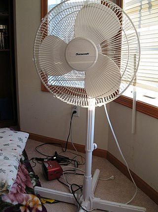
A fan is a powered machine used to create a flow of air. A fan consists of a rotating arrangement of vanes or blades, generally made of wood, plastic, or metal, which act on the air. The rotating assembly of blades and hub is known as an impeller, rotor, or runner. Usually, it is contained within some form of housing, or case. This may direct the airflow, or increase safety by preventing objects from contacting the fan blades. Most fans are powered by electric motors, but other sources of power may be used, including hydraulic motors, handcranks, and internal combustion engines.

A rotodynamic pump is a kinetic machine in which energy is continuously imparted to the pumped fluid by means of a rotating impeller, propeller, or rotor, in contrast to a positive displacement pump in which a fluid is moved by trapping a fixed amount of fluid and forcing the trapped volume into the pump's discharge. Examples of rotodynamic pumps include adding kinetic energy to a fluid such as by using a centrifugal pump to increase fluid velocity or pressure.

<span class="mw-page-title-main">Components of jet engines</span> Brief description of components needed for jet engines

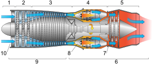
This article briefly describes the components and systems found in jet engines.

HVAC is a major sub discipline of mechanical engineering. The goal of HVAC design is to balance indoor environmental comfort with other factors such as installation cost, ease of maintenance, and energy efficiency. The discipline of HVAC includes a large number of specialized terms and acronyms, many of which are summarized in this glossary.

References

  1. http://www.howden.com/en/Products/default.htm
  2. "Air Movement and Control Association". AMCA . Retrieved 2008-05-05.