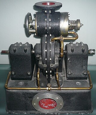
The Tesla turbine is a bladeless centripetal flow turbine invented by Nikola Tesla in 1913. Nozzles apply a moving fluid to the edges of a set of discs. The engine uses smooth discs rotating in a chamber to generate rotational movement due to the momentum exchange between the fluid and the discs. The discs are arranged in an orientation similar to a stack of CDs on a pole.

A labyrinth seal is a type of mechanical seal that provides a tortuous path to help prevent leakage. An example of such a seal is sometimes found within an axle's bearing to help prevent the leakage of the oil lubricating the bearing.

Centrifugal compressors, sometimes called impeller compressors or radial compressors, are a sub-class of dynamic axisymmetric work-absorbing turbomachinery.

An impeller, or impellor, is a driven rotor used to increase the pressure and flow of a fluid. It is the opposite of a turbine, which extracts energy from, and reduces the pressure of, a flowing fluid.

An axial compressor is a gas compressor that can continuously pressurize gases. It is a rotating, airfoil-based compressor in which the gas or working fluid principally flows parallel to the axis of rotation, or axially. This differs from other rotating compressors such as centrifugal compressor, axi-centrifugal compressors and mixed-flow compressors where the fluid flow will include a "radial component" through the compressor.

Turbomachinery, in mechanical engineering, describes machines that transfer energy between a rotor and a fluid, including both turbines and compressors. While a turbine transfers energy from a fluid to a rotor, a compressor transfers energy from a rotor to a fluid. It is an important application of fluid mechanics.
A compressor map is a chart which shows the performance of a turbomachinery compressor. This type of compressor is used in gas turbine engines, for supercharging reciprocating engines and for industrial processes, where it is known as a dynamic compressor. A map is created from compressor rig test results or predicted by a special computer program. Alternatively the map of a similar compressor can be suitably scaled. This article is an overview of compressor maps and their different applications and also has detailed explanations of maps for a fan and intermediate and high-pressure compressors from a three-shaft aero-engine as specific examples.
A jet engine performs by converting fuel into thrust. How well it performs is an indication of what proportion of its fuel goes to waste. It transfers heat from burning fuel to air passing through the engine. In doing so it produces thrust work when propelling a vehicle but a lot of the fuel is wasted and only appears as heat. Propulsion engineers aim to minimize the degradation of fuel energy into unusable thermal energy. Increased emphasis on performance improvements for commercial airliners came in the 1970s from the rising cost of fuel.

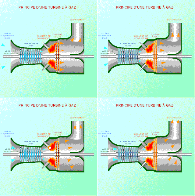
As the name suggests, gas turbine engine compressors provide the compression part of the gas turbine engine thermodynamic cycle. There are three basic categories of gas turbine engine compressor: axial compressor, centrifugal compressor and mixed flow compressor. A fourth, unusual, type is the free-piston gas generator, which combines the functions of compressor and combustion chamber in one unit.

A radial turbine is a turbine in which the flow of the working fluid is radial to the shaft. The difference between axial and radial turbines consists in the way the fluid flows through the components. Whereas for an axial turbine the rotor is 'impacted' by the fluid flow, for a radial turbine, the flow is smoothly orientated perpendicular to the rotation axis, and it drives the turbine in the same way water drives a watermill. The result is less mechanical stress which enables a radial turbine to be simpler, more robust, and more efficient when compared to axial turbines. When it comes to high power ranges the radial turbine is no longer competitive and the efficiency becomes similar to that of the axial turbines.
Industrial fans and blowers are machines whose primary function is to provide and accommodate a large flow of air or gas to various parts of a building or other structures. This is achieved by rotating a number of blades, connected to a hub and shaft, and driven by a motor or turbine. The flow rates of these mechanical fans range from approximately 200 cubic feet (5.7 m3) to 2,000,000 cubic feet (57,000 m3) per minute. A blower is another name for a fan that operates where the resistance to the flow is primarily on the downstream side of the fan.
In fluid dynamics, flow can be decomposed into primary flow plus secondary flow, a relatively weaker flow pattern superimposed on the stronger primary flow pattern. The primary flow is often chosen to be an exact solution to simplified or approximated governing equations, such as potential flow around a wing or geostrophic current or wind on the rotating Earth. In that case, the secondary flow usefully spotlights the effects of complicated real-world terms neglected in those approximated equations. For instance, the consequences of viscosity are spotlighted by secondary flow in the viscous boundary layer, resolving the tea leaf paradox. As another example, if the primary flow is taken to be a balanced flow approximation with net force equated to zero, then the secondary circulation helps spotlight acceleration due to the mild imbalance of forces. A smallness assumption about secondary flow also facilitates linearization.

The primary application of wind turbines is to generate energy using the wind. Hence, the aerodynamics is a very important aspect of wind turbines. Like most machines, wind turbines come in many different types, all of them based on different energy extraction concepts.
Cheng Xu is a Chinese American aerodynamic design engineer and engineering manager. He is a Fellow of the American Society of Mechanical Engineers and a member of the Technical Committee on Energy and Power Systems, IASTED. He also served as a guest editor of International Journal of Rotating Machinery.
In turbomachinery, degree of reaction or reaction ratio (R) is defined as the ratio of the static pressure rise in the rotating blades of a compressor (or drop in turbine blades) to the static pressure rise in the compressor stage (or drop in a turbine stage). Alternatively it is the ratio of static enthalpy change in the rotor to the static enthalpy change in the stage.
In turbomachinery, the slip factor is a measure of the fluid slip in the impeller of a compressor or a turbine, mostly a centrifugal machine. Fluid slip is the deviation in the angle at which the fluid leaves the impeller from the impeller's blade/vane angle. Being quite small in axial impellers, slip is a very important phenomenon in radial impellers and is useful in determining the accurate estimation of work input or the energy transfer between the impeller and the fluid, rise in pressure and the velocity triangles at the impeller exit.
Francis turbine converts energy at high pressure heads which are not easily available and hence a turbine was required to convert the energy at low pressure heads, given that the quantity of water was large enough. It was easy to convert high pressure heads to power easily but difficult to do so for low pressure heads. Therefore, an evolution took place that converted the Francis turbine to Kaplan turbine, which generated power at even low pressure heads efficiently.
An axial turbine is a turbine in which the flow of the working fluid is parallel to the shaft, as opposed to radial turbines, where the fluid runs around a shaft, as in a watermill. An axial turbine has a similar construction as an axial compressor, but it operates in the reverse, converting flow of the fluid into rotating mechanical energy.

Joseph Katz is an Israel-born American fluid dynamicist, known for his work on experimental fluid mechanics, cavitation phenomena and multiphase flow, turbulence, turbomachinery flows and oceanography flows, flow-induced vibrations and noise, and development of optical flow diagnostics techniques, including Particle Image Velocimetry (PIV) and Holographic Particle Image Velocimetry (HPIV). As of 2005, he is the William F. Ward Sr. Distinguished Professor at the Department of Mechanical Engineering of the Whiting School of Engineering at the Johns Hopkins University.
Radial means that the fluid is flowing in radial direction that is either from inward to outward or from outward to inward, with respect to the runner shaft axis. If the fluid is flowing from inward to outward then it is called outflow radial turbine.
- In this turbine, the working fluid enters around the axis of the wheel and then flows outwards.
- The guide vane mechanism is typically surrounded by the runner/turbine.
- In this turbine, the inner diameter of the runner is the inlet and outer diameter is an outlet.


