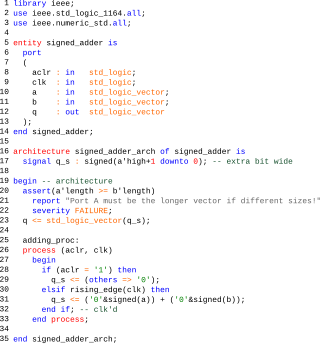
VHDL is a hardware description language that can model the behavior and structure of digital systems at multiple levels of abstraction, ranging from the system level down to that of logic gates, for design entry, documentation, and verification purposes. The language was developed for the US military VHSIC program in the 1980s, and has been standardized by the Institute of Electrical and Electronics Engineers (IEEE) as IEEE Std 1076; the latest version of which is IEEE Std 1076-2019. To model analog and mixed-signal systems, an IEEE-standardized HDL based on VHDL called VHDL-AMS has been developed.
Verilog, standardized as IEEE 1364, is a hardware description language (HDL) used to model electronic systems. It is most commonly used in the design and verification of digital circuits at the register-transfer level of abstraction. It is also used in the verification of analog circuits and mixed-signal circuits, as well as in the design of genetic circuits. In 2009, the Verilog standard was merged into the SystemVerilog standard, creating IEEE Standard 1800-2009. Since then, Verilog has been officially part of the SystemVerilog language. The current version is IEEE standard 1800-2023.

A programmable logic device (PLD) is an electronic component used to build reconfigurable digital circuits. Unlike digital logic constructed using discrete logic gates with fixed functions, the function of a PLD is undefined at the time of manufacture. Before the PLD can be used in a circuit it must be programmed to implement the desired function. Compared to fixed logic devices, programmable logic devices simplify the design of complex logic and may offer superior performance. Unlike for microprocessors, programming a PLD changes the connections made between the gates in the device.
In computer engineering, a hardware description language (HDL) is a specialized computer language used to describe the structure and behavior of electronic circuits, usually to design application-specific integrated circuits (ASICs) and to program field-programmable gate arrays (FPGAs).

AVR is a family of microcontrollers developed since 1996 by Atmel, acquired by Microchip Technology in 2016. These are modified Harvard architecture 8-bit RISC single-chip microcontrollers. AVR was one of the first microcontroller families to use on-chip flash memory for program storage, as opposed to one-time programmable ROM, EPROM, or EEPROM used by other microcontrollers at the time.

IEEE 488, also known as HP-IB and generically as GPIB, is a short-range digital communications 8-bit parallel multi-master interface bus specification developed by Hewlett-Packard. It subsequently became the subject of several standards.

The MSP430 is a mixed-signal microcontroller family from Texas Instruments, first introduced on 14 February 1992. Built around a 16-bit CPU, the MSP430 was designed for low power consumption, embedded applications and low cost.

A ball grid array (BGA) is a type of surface-mount packaging used for integrated circuits. BGA packages are used to permanently mount devices such as microprocessors. A BGA can provide more interconnection pins than can be put on a dual in-line or flat package. The whole bottom surface of the device can be used, instead of just the perimeter. The traces connecting the package's leads to the wires or balls which connect the die to package are also on average shorter than with a perimeter-only type, leading to better performance at high speeds.
Serial Peripheral Interface (SPI) is a de facto standard for synchronous serial communication, used primarily in embedded systems for short-distance wired communication between integrated circuits.
JTAG is an industry standard for verifying designs of and testing printed circuit boards after manufacture.

Accellera Systems Initiative (Accellera) is a standards organization that supports a mix of user and vendor standards and open interfaces development in the area of electronic design automation (EDA) and integrated circuit (IC) design and manufacturing. It is less constrained than the Institute of Electrical and Electronics Engineers (IEEE) and is therefore the starting place for many standards. Once mature and adopted by the broader community, the standards are usually transferred to the IEEE.

Automatic test equipment or automated test equipment (ATE) is any apparatus that performs tests on a device, known as the device under test (DUT), equipment under test (EUT) or unit under test (UUT), using automation to quickly perform measurements and evaluate the test results. An ATE can be a simple computer-controlled digital multimeter, or a complicated system containing dozens of complex test instruments capable of automatically testing and diagnosing faults in sophisticated electronic packaged parts or on wafer testing, including system on chips and integrated circuits.

Boundary scan is a method for testing interconnects on printed circuit boards or sub-blocks inside an integrated circuit. Boundary scan is also widely used as a debugging method to watch integrated circuit pin states, measure voltage, or analyze sub-blocks inside an integrated circuit.

Integrated circuit design, semiconductor design, chip design or IC design, is a sub-field of electronics engineering, encompassing the particular logic and circuit design techniques required to design integrated circuits, or ICs. ICs consist of miniaturized electronic components built into an electrical network on a monolithic semiconductor substrate by photolithography.
Nexus or IEEE-ISTO 5001-2003 is a standard debugging interface for embedded systems.
Serial Vector Format (SVF) is a file format that contains boundary scan vectors to be sent to an electronic circuit using a JTAG interface. Boundary scan vectors consist of the following data:

In integrated circuit design, physical design is a step in the standard design cycle which follows after the circuit design. At this step, circuit representations of the components of the design are converted into geometric representations of shapes which, when manufactured in the corresponding layers of materials, will ensure the required functioning of the components. This geometric representation is called integrated circuit layout. This step is usually split into several sub-steps, which include both design and verification and validation of the layout.
The Design Automation Standards Committee (DASC) is a subgroup of interested individuals members of the Institute of Electrical and Electronics Engineers (IEEE) Computer Society and Standards Association. It oversees IEEE Standards that are related to computer-aided design. It is part of the IEEE Computer Society.
In the electronics industry, embedded instrumentation refers to the integration of test and measurement instrumentation into semiconductor chips. Embedded instrumentation differs from embedded system, which are electronic systems or subsystems that usually comprise the control portion of a larger electronic system. Instrumentation embedded into chips is employed in a variety of electronic test applications, including validating and testing chips themselves, validating, testing and debugging the circuit boards where these chips are deployed, and troubleshooting systems once they have been installed in the field.
MIPI Alliance Debug Architecture provides a standardized infrastructure for debugging deeply embedded systems in the mobile and mobile-influenced space. The MIPI Alliance MIPI Debug Working Group has released a portfolio of specifications; their objective is to provide standard debug protocols and standard interfaces from a system on a chip (SoC) to the debug tool. The whitepaper Architecture Overview for Debug summarizes all the efforts. In recent years, the group focused on specifying protocols that improve the visibility of the internal operations of deeply embedded systems, standardizing debug solutions via the functional interfaces of form factor devices, and specifying the use of I3C as debugging bus.