Bump steer causes a vehicle to turn itself when one wheel hits a bump or falls down into a hole or rut. Excessive bump steer increases tire wear and makes the vehicle more difficult to handle on rough roads. For example, if the front left wheel rolls over a bump it will compress the suspension on that corner and automatically rotate to the left (toe out), causing the car to turn itself left momentarily without any input from the steering wheel. Another example is that when most vehicles become airborne their front wheels will noticeably toe in.[citation needed]
Rear suspension can be designed a number of ways. Many modern vehicles have rear suspension designs which are opposite of the front suspension: Toe in under bump, and out under droop. They can also be designed to have very little or no bump steer at all. Cars with rear live axles, also known as solid axles do not exhibit true bump steer, but can still cause some steering over one wheel bumps, see §difference between bump steer and roll steer. If both wheels on a live axle move upwards by the same amount, they tend not to steer.
The linearity of the bump steer curve is important and relies on the relationship of the control arms and tie rod pickup points, and the length of each part. As the suspension goes through bump and droop, each part follows an arc resulting in a change of effective length. Whichever parts are longest tend to have less change in effective length because their arc radius is longer. This is the determining factor in designed bump steer. Another factor that affects bump steer is bushing compliance and deflection and arm bending. During a turn, if some or all of the bushings deflect then their pickup points have changed If any of the arms and tie rods bend then their effective length will change resulting in a change of toe.
Bump steer and car ride height
Bump steer can become a problem when cars are modified by lowering or lifting, when a spring has become worn or broken causing a lower ride height, or if the vehicle is heavily loaded. When a car is lowered or lifted, the wheels' toe setting will change.
When a car is lowered or lifted, it will have to be re-aligned to avoid excessive tire wear. This is accomplished through adjustment of the steering tie rod length. After the tie rod lengths are changed, bump steer values will also change. In some cases, the car will have less toe change, this can make the car exhibit less roll understeer and therefore feel more "twitchy" during a turn. Other vehicles after lowering will exhibit an increase in toe change compared to stock, this results in the car feeling very "twitchy" on straight, bumpy roads, and at the same time feeling unwilling to turn requiring more driver input than normal due to an increase in roll understeer.
When a vehicle is heavily loaded, it lowers the ride height. Typically cars are loaded by having heavy loads in the trunk, many passengers or towing a trailer, thus mainly affecting the rear wheels. When a car has been heavily loaded (if it does not have a live rear axle), the suspension will compress greatly in order to support the load resulting in an extreme amount of toe in on the rear wheels. This causes rapid tire wear, can cause the car to follow cracks in the road and can cause tire temperatures to rise higher than normal due to an increase in friction. Negative Camber will often be greatly increased as well. This results in very heavy inner tire wear on the rear wheels of a car that is heavily loaded or towing. One reason that most trucks have live axle rear suspensions is because it completely avoids toe and camber changes with a load. Cars with multi-link rear suspension should have an alignment while loaded if they are going to be operated under heavy loads for extended periods.
Difference between bump steer and roll steer
During a bump, both wheels rise together. When rolling as the car leans during a curve, the inside suspension extends and the outside suspension compresses. Typically this produces "toe in" on one wheel, and "toe out" on the other, thus producing a steering effect.
Cars with rear live axles, also known as solid axles, tend to not have true bump steer. Since both wheels are connected to a single, rigid member they are incapable of having any toe angles under normal conditions. Rear live axle suspensions are therefore designed to exhibit roll understeer. During a curve, the entire axle will turn slightly to face the inside of the curve so that the car does not turn more sharply than anticipated by the driver, roll understeer. It is possible to design a rear live axle suspension that exhibits roll oversteer but it is highly undesirable for on road use. Roll oversteer is sometimes incorporated on extreme off-road vehicles because it can allow the rear wheels to help turn the vehicle extremely sharply in tight trail conditions.
Roll steer is usually measured in degrees of toe per degree of roll, but can also be measured in degrees of toe per metre of wheel travel.
Method of adjustment
The linearity of the bump steer curve is important and relies on the relationship of the control arms and tie rod pickup points, and the length of each part.
If the wheels are not properly aligned then the length of the tie rod needs to be adjusted. Usually only small adjustments in the range of millimeters or 16ths of an inch are required.
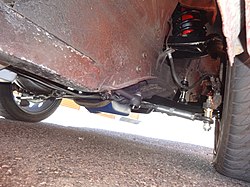
Bump steer kit installed on 1965 Ford Mustang
Bump steer can be adjusted by moving any of the front suspension components pickup points Up, down, in or out. For example: Say the inner tie rod mounting point is moved up either by moving the rack or modifying the pitman arm mounting point or arm drop. The result is the tie rod's arc will change. It will then require a change in the tie rod length to be in proper alignment so the radius of the arc will change as well. If the radius arc of the tie rod is longer than stock on a front steer setup then the car will have more toe understeer. If the same scenario was applied to a rear steering design, then the car would exhibit less toe understeer. This is because the effective length of the tie rods is affected by its static length/arc radius, its pickup points and the angle of its arc during each phase of suspension travel in relation to the control arms.
This page is based on this Wikipedia article Text is available under the CC BY-SA 4.0 license; additional terms may apply. Images, videos and audio are available under their respective licenses.