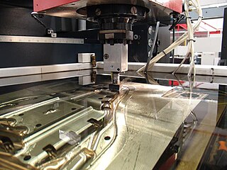
Electrical discharge machining (EDM), also known as spark machining, spark eroding, die sinking, wire burning or wire erosion, is a metal fabrication process whereby a desired shape is obtained by using electrical discharges (sparks). Material is removed from the work piece by a series of rapidly recurring current discharges between two electrodes, separated by a dielectric liquid and subject to an electric voltage. One of the electrodes is called the tool-electrode, or simply the tool or electrode, while the other is called the workpiece-electrode, or work piece. The process depends upon the tool and work piece not making physical contact.

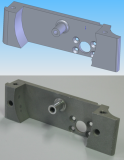
Computer-aided manufacturing (CAM) also known as computer-aided modeling or computer-aided machining is the use of software to control machine tools in the manufacturing of work pieces. This is not the only definition for CAM, but it is the most common; CAM may also refer to the use of a computer to assist in all operations of a manufacturing plant, including planning, management, transportation and storage. Its primary purpose is to create a faster production process and components and tooling with more precise dimensions and material consistency, which in some cases, uses only the required amount of raw material, while simultaneously reducing energy consumption. CAM is now a system used in schools and lower educational purposes. CAM is a subsequent computer-aided process after computer-aided design (CAD) and sometimes computer-aided engineering (CAE), as the model generated in CAD and verified in CAE can be input into CAM software, which then controls the machine tool. CAM is used in many schools alongside computer-aided design (CAD) to create objects.

Metalworking is the process of shaping and reshaping metals to create useful objects, parts, assemblies, and large scale structures. As a term it covers a wide and diverse range of processes, skills, and tools for producing objects on every scale: from huge ships, buildings, and bridges down to precise engine parts and delicate jewelry.

Machining is a process in which a material is cut to a desired final shape and size by a controlled material-removal process. The processes that have this common theme are collectively called subtractive manufacturing, which utilizes machine tools, in contrast to additive manufacturing, which uses controlled addition of material.

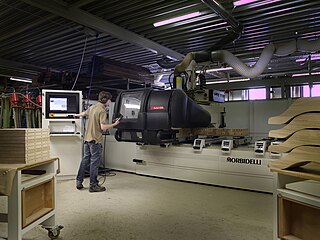
Numerical control is the automated control of machining tools by means of a computer. A CNC machine processes a piece of material to meet specifications by following coded programmed instructions and without a manual operator directly controlling the machining operation.

Drilling is a cutting process that uses a drill bit to cut a hole of circular cross-section in solid materials. The drill bit is usually a rotary cutting tool, often multi-point. The bit is pressed against the work-piece and rotated at rates from hundreds to thousands of revolutions per minute. This forces the cutting edge against the work-piece, cutting off chips (swarf) from the hole as it is drilled.

Printed circuit board milling is the process of removing areas of copper from a sheet of printed circuit board material to recreate the pads, signal traces and structures according to patterns from a digital circuit board plan known as a layout file. Similar to the more common and well known chemical PCB etch process, the PCB milling process is subtractive: material is removed to create the electrical isolation and ground planes required. However, unlike the chemical etch process, PCB milling is typically a non-chemical process and as such it can be completed in a typical office or lab environment without exposure to hazardous chemicals. High quality circuit boards can be produced using either process. In the case of PCB milling, the quality of a circuit board is chiefly determined by the system's true, or weighted, milling accuracy and control as well as the condition of the milling bits and their respective feed/rotational speeds. By contrast, in the chemical etch process, the quality of a circuit board depends on the accuracy and/or quality of the mask used to protect the copper from the chemicals and the state of the etching chemicals.

The phrase speeds and feeds or feeds and speeds refers to two separate velocities in machine tool practice, cutting speed and feed rate. They are often considered as a pair because of their combined effect on the cutting process. Each, however, can also be considered and analyzed in its own right.
A grinding dresser or wheel dresser is a tool to dress the surface of a grinding wheel. Grinding dressers are used to return a wheel to its original round shape, to expose fresh grains for renewed cutting action, or to make a different profile on the wheel's edge. Utilizing pre-determined dressing parameters will allow the wheel to be conditioned for optimum grinding performance while truing and restoring the form simultaneously.

A Tool and Cutter Grinder is used to sharpen milling cutters and tool bits along with a host of other cutting tools.
Milling cutters are cutting tools typically used in milling machines or machining centres to perform milling operations. They remove material by their movement within the machine or directly from the cutter's shape.

A metal lathe or metalworking lathe is a large class of lathes designed for precisely machining relatively hard materials. They were originally designed to machine metals; however, with the advent of plastics and other materials, and with their inherent versatility, they are used in a wide range of applications, and a broad range of materials. In machining jargon, where the larger context is already understood, they are usually simply called lathes, or else referred to by more-specific subtype names. These rigid machine tools remove material from a rotating workpiece via the movements of various cutting tools, such as tool bits and drill bits.
In the context of machining, a cutting tool or cutter is typically a hardened metal tool that is used to cut, shape, and remove material from a workpiece by means of machining tools as well as abrasive tools by way of shear deformation. The majority of these tools are designed exclusively for metals. There are several different types of single edge cutting tools that are made from a variety of hardened metal alloys that are ground to a specific shape in order to perform a specific part of the turning process resulting in a finished machined part. Single edge cutting tools are used mainly in the turning operations performed by a lathe in which they vary in size as well as alloy composition depending on the size and the type of material being turned. These cutting tools are held stationary by what is known as a tool post which is what manipulates the tools to cut the material into the desired shape. Single edge cutting tools are also the means of cutting material performed by metal shaping machines and metal planing machines which removes material by means of one cutting edge. Milling and drilling tools are often multipoint tools. Drilling is exclusively used to make holes in a workpiece. All drill bits have two cutting edges that are ground into two equally tapered angles which cuts through the material by applying downward rotational force. Endmills or milling bits, which also cut material by rotational force. Although these tools are not made to put holes in a workpiece. They cut by horizontal shear deformation in which the workpiece is brought into the tool as it's rotating. This is known as the tool path which is determined by the axis of the table that is holding the workpiece in place. This table is designed to accept a variety of vises and clamping tools so that it can move into the cutter at various angles and directions while the workpiece remains still. There are several different types of endmills that perform a certain type of milling action.
Incremental sheet forming is a sheet metal forming technique where a sheet is formed into the final workpiece by a series of small incremental deformations. However, studies have shown that it can be applied to polymer and composite sheets too. Generally, the sheet is formed by a round tipped tool, typically 5 to 20mm in diameter. The tool, which can be attached to a CNC machine, a robot arm or similar, indents into the sheet by about 1 mm and follows a contour for the desired part. It then indents further and draws the next contour for the part into the sheet and continues to do this until the full part is formed. ISF can be divided into variants depending on the number of contact points between tool, sheet and die. The term Single Point Incremental Forming (SPIF) is used when the opposite side of the sheet is supported by a faceplate and Two Point Incremental Forming (TPIF) when a full or partial die supports the sheet.
In manufacturing, threading is the process of creating a screw thread. More screw threads are produced each year than any other machine element. There are many methods of generating threads, including subtractive methods ; deformative or transformative methods ; additive methods ; or combinations thereof.
Arbor milling is a cutting process which removes material via a multi-toothed cutter. An arbor mill is a type of milling machine characterized by its ability to rapidly remove material from a variety of materials. This milling process is not fax rapid but also versatile.
Facing in machining can be used in two different areas: facing on a milling machine and facing on a lathe. Facing on the milling machine involves various milling operations, but primarily face milling. On the lathe, facing is commonly used in turning and boring operations. Other operations remove material in ways similar to facing, for example, planing, shaping, and grinding, but these processes are not labeled by the term "facing."

WorkNC is a Computer aided manufacturing (CAM) software developed by Sescoi for multi-axis machining.

Milling is the process of machining using rotary cutters to remove material by advancing a cutter into a workpiece. This may be done by varying direction on one or several axes, cutter head speed, and pressure. Milling covers a wide variety of different operations and machines, on scales from small individual parts to large, heavy-duty gang milling operations. It is one of the most commonly used processes for machining custom parts to precise tolerances.
Virtual machining is the practice of using computers to simulate and model the use of machine tools for part manufacturing. Such activity replicates the behavior and errors of a real environment in virtual reality systems. This can provide useful ways to manufacture products without physical testing on the shop floor. As a result, time and cost of part production can be decreased.


