
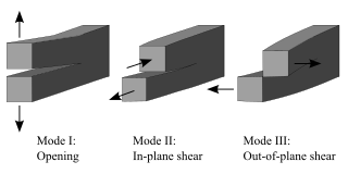
Fracture is the appearance of a crack or complete separation of an object or material into two or more pieces under the action of stress. The fracture of a solid usually occurs due to the development of certain displacement discontinuity surfaces within the solid. If a displacement develops perpendicular to the surface, it is called a normal tensile crack or simply a crack; if a displacement develops tangentially, it is called a shear crack, slip band, or dislocation.
Fracture mechanics is the field of mechanics concerned with the study of the propagation of cracks in materials. It uses methods of analytical solid mechanics to calculate the driving force on a crack and those of experimental solid mechanics to characterize the material's resistance to fracture.
Mohr–Coulomb theory is a mathematical model describing the response of brittle materials such as concrete, or rubble piles, to shear stress as well as normal stress. Most of the classical engineering materials follow this rule in at least a portion of their shear failure envelope. Generally the theory applies to materials for which the compressive strength far exceeds the tensile strength.
Thermal shock is a phenomenon characterized by a rapid change in temperature that results in a transient mechanical load on an object. The load is caused by the differential expansion of different parts of the object due to the temperature change. This differential expansion can be understood in terms of strain, rather than stress. When the strain exceeds the tensile strength of the material, it can cause cracks to form, and eventually lead to structural failure.

Crazing is a yielding mechanism in polymers characterized by the formation of a fine network of microvoids and fibrils. These structures typically appear as linear features and frequently precede brittle fracture. The fundamental difference between crazes and cracks is that crazes contain polymer fibrils, constituting about 50% of their volume, whereas cracks do not. Unlike cracks, crazes can transmit load between their two faces through these fibrils.
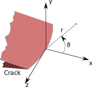
In fracture mechanics, the stress intensity factor is used to predict the stress state near the tip of a crack or notch caused by a remote load or residual stresses. It is a theoretical construct usually applied to a homogeneous, linear elastic material and is useful for providing a failure criterion for brittle materials, and is a critical technique in the discipline of damage tolerance. The concept can also be applied to materials that exhibit small-scale yielding at a crack tip.
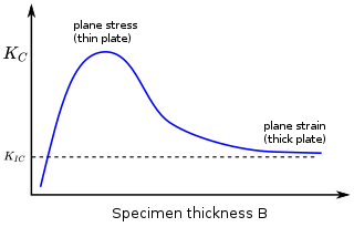
In materials science, fracture toughness is the critical stress intensity factor of a sharp crack where propagation of the crack suddenly becomes rapid and unlimited. A component's thickness affects the constraint conditions at the tip of a crack with thin components having plane stress conditions and thick components having plane strain conditions. Plane strain conditions give the lowest fracture toughness value which is a material property. The critical value of stress intensity factor in mode I loading measured under plane strain conditions is known as the plane strain fracture toughness, denoted . When a test fails to meet the thickness and other test requirements that are in place to ensure plane strain conditions, the fracture toughness value produced is given the designation . Fracture toughness is a quantitative way of expressing a material's resistance to crack propagation and standard values for a given material are generally available.
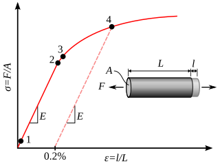
In materials science and engineering, the yield point is the point on a stress–strain curve that indicates the limit of elastic behavior and the beginning of plastic behavior. Below the yield point, a material will deform elastically and will return to its original shape when the applied stress is removed. Once the yield point is passed, some fraction of the deformation will be permanent and non-reversible and is known as plastic deformation.

The three-point bending flexural test provides values for the modulus of elasticity in bending , flexural stress , flexural strain and the flexural stress–strain response of the material. This test is performed on a universal testing machine with a three-point or four-point bend fixture. The main advantage of a three-point flexural test is the ease of the specimen preparation and testing. However, this method has also some disadvantages: the results of the testing method are sensitive to specimen and loading geometry and strain rate.
The J-integral represents a way to calculate the strain energy release rate, or work (energy) per unit fracture surface area, in a material. The theoretical concept of J-integral was developed in 1967 by G. P. Cherepanov and independently in 1968 by James R. Rice, who showed that an energetic contour path integral was independent of the path around a crack.

Contact mechanics is the study of the deformation of solids that touch each other at one or more points. A central distinction in contact mechanics is between stresses acting perpendicular to the contacting bodies' surfaces and frictional stresses acting tangentially between the surfaces. Normal contact mechanics or frictionless contact mechanics focuses on normal stresses caused by applied normal forces and by the adhesion present on surfaces in close contact, even if they are clean and dry. Frictional contact mechanics emphasizes the effect of friction forces.
Material failure theory is an interdisciplinary field of materials science and solid mechanics which attempts to predict the conditions under which solid materials fail under the action of external loads. The failure of a material is usually classified into brittle failure (fracture) or ductile failure (yield). Depending on the conditions most materials can fail in a brittle or ductile manner or both. However, for most practical situations, a material may be classified as either brittle or ductile.

According to the classical theories of elastic or plastic structures made from a material with non-random strength (ft), the nominal strength (σN) of a structure is independent of the structure size (D) when geometrically similar structures are considered. Any deviation from this property is called the size effect. For example, conventional strength of materials predicts that a large beam and a tiny beam will fail at the same stress if they are made of the same material. In the real world, because of size effects, a larger beam will fail at a lower stress than a smaller beam.
Polymer fracture is the study of the fracture surface of an already failed material to determine the method of crack formation and extension in polymers both fiber reinforced and otherwise. Failure in polymer components can occur at relatively low stress levels, far below the tensile strength because of four major reasons: long term stress or creep rupture, cyclic stresses or fatigue, the presence of structural flaws and stress-cracking agents. Formations of submicroscopic cracks in polymers under load have been studied by x ray scattering techniques and the main regularities of crack formation under different loading conditions have been analyzed. The low strength of polymers compared to theoretically predicted values are mainly due to the many microscopic imperfections found in the material. These defects namely dislocations, crystalline boundaries, amorphous interlayers and block structure can all lead to the non-uniform distribution of mechanical stress.

Crack tip opening displacement (CTOD) or is the distance between the opposite faces of a crack tip at the 90° intercept position. The position behind the crack tip at which the distance is measured is arbitrary but commonly used is the point where two 45° lines, starting at the crack tip, intersect the crack faces. The parameter is used in fracture mechanics to characterize the loading on a crack and can be related to other crack tip loading parameters such as the stress intensity factor and the elastic-plastic J-integral.
The microplane model, conceived in 1984, is a material constitutive model for progressive softening damage. Its advantage over the classical tensorial constitutive models is that it can capture the oriented nature of damage such as tensile cracking, slip, friction, and compression splitting, as well as the orientation of fiber reinforcement. Another advantage is that the anisotropy of materials such as gas shale or fiber composites can be effectively represented. To prevent unstable strain localization, this model must be used in combination with some nonlocal continuum formulation. Prior to 2000, these advantages were outweighed by greater computational demands of the material subroutine, but thanks to huge increase of computer power, the microplane model is now routinely used in computer programs, even with tens of millions of finite elements.
The theoretical strength of a solid is the maximum possible stress a perfect solid can withstand. It is often much higher than what current real materials can achieve. The lowered fracture stress is due to defects, such as interior or surface cracks. One of the goals for the study of mechanical properties of materials is to design and fabricate materials exhibiting strength close to the theoretical limit.
The fracture of soft materials involves large deformations and crack blunting before propagation of the crack can occur. Consequently, the stress field close to the crack tip is significantly different from the traditional formulation encountered in the Linear elastic fracture mechanics. Therefore, fracture analysis for these applications requires a special attention. The Linear Elastic Fracture Mechanics (LEFM) and K-field are based on the assumption of infinitesimal deformation, and as a result are not suitable to describe the fracture of soft materials. However, LEFM general approach can be applied to understand the basics of fracture on soft materials. The solution for the deformation and crack stress field in soft materials considers large deformation and is derived from the finite strain elastostatics framework and hyperelastic material models.

A crack growth equation is used for calculating the size of a fatigue crack growing from cyclic loads. The growth of a fatigue crack can result in catastrophic failure, particularly in the case of aircraft. When many growing fatigue cracks interact with one another it is known as widespread fatigue damage. A crack growth equation can be used to ensure safety, both in the design phase and during operation, by predicting the size of cracks. In critical structure, loads can be recorded and used to predict the size of cracks to ensure maintenance or retirement occurs prior to any of the cracks failing. Safety factors are used to reduce the predicted fatigue life to a service fatigue life because of the sensitivity of the fatigue life to the size and shape of crack initiating defects and the variability between assumed loading and actual loading experienced by a component.
Fastran is a computer program for calculating the rate of fatigue crack growth by combining crack growth equations and a simulation of the plasticity at the crack tip.


