Related Research Articles

An amplifier, electronic amplifier or (informally) amp is an electronic device that can increase the magnitude of a signal. It is a two-port electronic circuit that uses electric power from a power supply to increase the amplitude of a signal applied to its input terminals, producing a proportionally greater amplitude signal at its output. The amount of amplification provided by an amplifier is measured by its gain: the ratio of output voltage, current, or power to input. An amplifier is defined as a circuit that has a power gain greater than one.

In signal processing, pre-emphasis is a technique to protect against anticipated noise and loss. The idea is to boost the frequency range that is most susceptible to noise and loss beforehand, so that after a noisy and lossy process more information can be recovered from that frequency range. Removal of the distortion caused by pre-emphasis is called de-emphasis, making the output accurately reproduce the original input.

An electrical cable is an assembly of one or more wires running side by side or bundled, which is used as an electrical conductor to carry electric current.
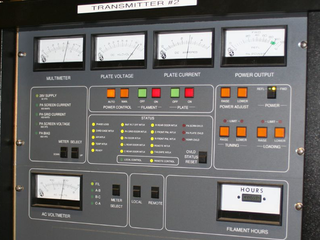
In electronics and telecommunications, a radio transmitter or just transmitter is an electronic device which produces radio waves with an antenna with the purpose of signal transmission up to a radio receiver. The transmitter itself generates a radio frequency alternating current, which is applied to the antenna. When excited by this alternating current, the antenna radiates radio waves.
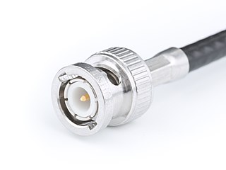
The BNC connector is a miniature quick connect/disconnect radio frequency connector used for coaxial cable. It is designed to maintain the same characteristic impedance of the cable, with 50 ohm and 75 ohm types being made. It is usually applied for video and radio frequency connections up to about 2 GHz and up to 500 volts. The connector has a twist to lock design with two lugs in the female portion of the connector engaging a slot in the shell of the male portion. The type was introduced on military radio equipment in the 1940s and has since become widely applied in radio systems, and is a common type of video connector. Similar radio-frequency connectors differ in dimensions and attachment features, and may allow for higher voltages, higher frequencies, or three-wire connections.

In radio engineering, an antenna or aerial is an electronic device that converts an alternating electric current into radio waves, or radio waves into an electric current. It is the interface between radio waves propagating through space and electric currents moving in metal conductors, used with a transmitter or receiver. In transmission, a radio transmitter supplies an electric current to the antenna's terminals, and the antenna radiates the energy from the current as electromagnetic waves. In reception, an antenna intercepts some of the power of a radio wave in order to produce an electric current at its terminals, that is applied to a receiver to be amplified. Antennas are essential components of all radio equipment.

In electrical engineering, impedance matching is the practice of designing or adjusting the input impedance or output impedance of an electrical device for a desired value. Often, the desired value is selected to maximize power transfer or minimize signal reflection. For example, impedance matching typically is used to improve power transfer from a radio transmitter via the interconnecting transmission line to the antenna. Signals on a transmission line will be transmitted without reflections if the transmission line is terminated with a matching impedance.

In electronics, electrical termination is the practice of ending a transmission line with a device that matches the characteristic impedance of the line. Termination prevents signals from reflecting off the end of the transmission line. Reflections at the ends of unterminated transmission lines cause distortion, which can produce ambiguous digital signal levels and misoperation of digital systems. Reflections in analog signal systems cause such effects as video ghosting, or power loss in radio transmitter transmission lines.
An antenna tuner, a matchbox, transmatch, antenna tuning unit (ATU), antenna coupler, or feedline coupler is a device connected between a radio transmitter or receiver and its antenna to improve power transfer between them by matching the impedance of the radio to the antenna's feedline. Antenna tuners are particularly important for use with transmitters. Transmitters feed power into a resistive load, very often 50 ohms, for which the transmitter is optimally designed for power output, efficiency, and low distortion. If the load seen by the transmitter departs from this design value due to improper tuning of the antenna/feedline combination the power output will change, distortion may occur and the transmitter may overheat.

A sound reinforcement system is the combination of microphones, signal processors, amplifiers, and loudspeakers in enclosures all controlled by a mixing console that makes live or pre-recorded sounds louder and may also distribute those sounds to a larger or more distant audience. In many situations, a sound reinforcement system is also used to enhance or alter the sound of the sources on the stage, typically by using electronic effects, such as reverb, as opposed to simply amplifying the sources unaltered.
Transmit diversity is radio communication using signals that originate from two or more independent sources that have been modulated with identical information-bearing signals and that may vary in their transmission characteristics at any given instant.
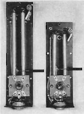
In microwave and radio-frequency engineering, a stub or resonant stub is a length of transmission line or waveguide that is connected at one end only. The free end of the stub is either left open-circuit, or short-circuited. Neglecting transmission line losses, the input impedance of the stub is purely reactive; either capacitive or inductive, depending on the electrical length of the stub, and on whether it is open or short circuit. Stubs may thus function as capacitors, inductors and resonant circuits at radio frequencies.

In radio reception, radio noise is unwanted random radio frequency electrical signals, fluctuating voltages, always present in a radio receiver in addition to the desired radio signal. Radio noise near in frequency to the radio signal being received interferes with it in the receiver's circuits. Radio noise is a combination of natural electromagnetic atmospheric noise created by electrical processes in the atmosphere like lightning, manmade radio frequency interference (RFI) from other electrical devices picked up by the receiver's antenna, and thermal noise present in the receiver input circuits, caused by the random thermal motion of molecules.
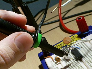
A test probe is a physical device used to connect electronic test equipment to a device under test (DUT). Test probes range from very simple, robust devices to complex probes that are sophisticated, expensive, and fragile. Specific types include test prods, oscilloscope probes and current probes. A test probe is often supplied as a test lead, which includes the probe, cable and terminating connector.
Attenuation distortion is the distortion of an analog signal that occurs during transmission when the transmission medium does not have a flat frequency response across the bandwidth of the medium or the frequency spectrum of the signal.

Otto Julius Zobel was an electrical engineer who worked for the American Telephone & Telegraph Company (AT&T) in the early part of the 20th century. Zobel's work on filter design was revolutionary and led, in conjunction with the work of John R. Carson, to significant commercial advances for AT&T in the field of frequency-division multiplex (FDM) telephone transmissions.
Nominal impedance in electrical engineering and audio engineering refers to the approximate designed impedance of an electrical circuit or device. The term is applied in a number of different fields, most often being encountered in respect of:

Equalization, or simply EQ, in sound recording and reproduction is the process of adjusting the volume of different frequency bands within an audio signal. The circuit or equipment used to achieve this is called an equalizer.
This glossary of electrical and electronics engineering is a list of definitions of terms and concepts related specifically to electrical engineering and electronics engineering. For terms related to engineering in general, see Glossary of engineering.
Lattice and bridged-T equalizers are circuits which are used to correct for the amplitude and/or phase errors of a network or transmission line. Usually, the aim is to achieve an overall system performance with a flat amplitude response and constant delay over a prescribed frequency range, by the addition of an equalizer. In the past, designers have used a variety of techniques to realize their equalizer circuits. These include the method of complementary networks; the method of straight line asymptotes; using a purpose built test-jig; the use of standard circuit building blocks,; or with the aid of computer programs. In addition, trial and error methods have been found to be surprisingly effective, when performed by an experienced designer.
References
![]() This article incorporates public domain material from Federal Standard 1037C. General Services Administration. Archived from the original on 2022-01-22. (in support of MIL-STD-188).
This article incorporates public domain material from Federal Standard 1037C. General Services Administration. Archived from the original on 2022-01-22. (in support of MIL-STD-188).