Core architecture data model (CADM) in enterprise architecture is a logical data model of information used to describe and build architectures. [2]
The CADM is essentially a common database schema, defined within the US Department of Defense Architecture Framework DoDAF. It was initially published in 1997 as a logical data model for architecture data. [3]
Core architecture data model (CADM) is designed to capture DoDAF architecture information in a standardized structure. [4] CADM was developed to support the data requirements of the DoDAF. The CADM defines the entities and relationships for DoDAF architecture data elements that enable integration within and across architecture descriptions. In this manner, the CADM supports the exchange of architecture information among mission areas, components, and federal and coalition partners, thus facilitating the data interoperability of architectures. [5]
CADM is a critical aspect of being able to integrate architectures in conformance with DoDAF. This includes the use of common data element definitions, semantics, and data structure for all architecture description entities or objects. The use of the underlying CADM faithfully relates common objects across multiple views. Adherence with the framework, which includes conformance with the currently approved version of CADM, provides both a common approach for developing architectures and a basic foundation for relating architectures. Conformance with the CADM ensures the use of common architecture data elements (or types). [5]
The CADM was initially published in 1997 as a logical data model for architecture data. It was revised in 1998 to meet all the requirements of the C4ISR Architecture Framework Version 2.0.1 As a logical data model, the initial CADM provided a conceptual view of how architecture information is organized. It identified and defined entities, attributes, and relations. The CADM has evolved since 1998, so that it now has a physical view providing the data types, abbreviated physical names, and domain values that are needed for a database implementation. Because the CADM is also a physical data model, it constitutes a database design and can be used to automatically generate databases. [3]
The CADM v1.01 was released with the DoD Architecture Framework v1.0 in August 2003. This DoDAF version restructured the C4ISR Framework v2.0 to offer guidance, product descriptions, and supplementary information in two volumes and a desk book. It broadened the applicability of architecture tenets and practices to all mission areas rather than just the C4ISR community. This document addressed usage, integrated architectures, DoD and Federal policies, value of architecture, architecture measures, DoD decision support processes, development techniques, analytical techniques, and the CADM v1.01, and moved towards a repository-based approach by placing emphasis on architecture data elements that comprise architecture products. [5]
The CADM v1.5 was pre-released with the DoD Architecture Framework, v1.5 in April 2007. The DoDAF v1.5 was an evolution of the DoDAF v1.0 and reflects and leverages the experience that the DoD components have gained in developing and using architecture descriptions. This transitional version provided additional guidance on how to reflect net-centric concepts within architecture descriptions, includes information on architecture data management and federating architectures through the department, and incorporates the pre-release CADM v1.5, a simplified model of previous CADM versions that includes net-centric elements. Pre-release CADM v1.5 is also backward compatible with previous CADM versions. Data sets built in accordance with the vocabulary of CADM v1.02/1.03 can be expressed faithfully and completely using the constructs of CADM v1.5. [5]
Note: For DoDAF V2.0, The DoDAF Meta-model (DM2) is working to replace the core architecture data model (CADM) which supported previous versions of the DoDAF. DM2 is a data construct that facilitates reader understanding of the use of data within an architecture document. CADM can continue to be used in support of architectures created in previous versions of DoDAF.
The major elements of a core architecture data model are described as follows: [3]
The DoDAF incorporates data modeling (CADM) and visualization aspects (products and views) to support architecture analysis. The DoDAF's data model, CADM, defines architecture data entities, the relationships between them, and the data entity attributes, essentially specifying the “grammar” for the architecture community. It contains a set of “nouns,” “verbs,” and “adjectives” that, together with the “grammar,” allow one to create “sentences” about architecture artifacts that are consistent with the DoDAF. The CADM is a necessary aspect of the architecture and provides the meaning behind the architectural visual representations (products). It enables the effective comparing and sharing of architecture data across the enterprise, contributing to the overall usefulness of architectures. The CADM describes the following data model levels in further detail: [5]
Data visualization is a way of graphically or textually representing architecture data to support decision-making analysis. The DoDAF provides products as a way of representing the underlying data in a user-friendly manner. In some cases, the existing DoDAF products are sufficient for representing the required information. Regardless of how one chooses to represent the architecture description, the underlying data (CADM) remains consistent, providing a common foundation to which analysis requirements are mapped. [5]
As illustrated in the figure, boxes represent entities for which architecture data are collected (representing tables when used for a relational database); they are depicted by open boxes with square corners (independent entities) or rounded corners (dependent entities). The entity name is outside and on top of the open box. The lines of text inside the box denote the attributes of that entity (representing columns in the entity table when used for a relational database). The horizontal line in each box separates the primary key attributes (used to find unique instances of the entity) from the non-key descriptive attributes. [1]
The symbol with a circle and line underneath indicates subtyping, for which all the entities connected below are non-overlapping subsets of the entity connected at the top of the symbol. Relationships are represented by dotted (non-identifying) and solid (identifying) relationships in which the child entity (the one nearest the solid dot) has zero, one, or many instances associated to each instance of the parent entity (the other entity connected by the relationship line). [1]
An architecture data repository responsive to the architecture products of the DoDAF contains information on basic architectural elements such as the following: [3]
The depicted (conceptual) relationships shown in this diagram include the following (among many others): [3]
With these relationships, many types of architectural and related information can be represented such as networks, information flows, information requirements, interfaces, and so forth. [3]
The counterpart to CADM within NASA is the NASA Exploration Information Ontology Model (NeXIOM), which is designed to capture and expressively describe the engineering and programmatic data that drives exploration program decisions. NeXIOM is intended to be a repository that can be accessed by various simulation tools and models that need to exchange information and data. [4]
In computing, a database is an organized collection of data stored and accessed electronically. Small databases can be stored on a file system, while large databases are hosted on computer clusters or cloud storage. The design of databases spans formal techniques and practical considerations, including data modeling, efficient data representation and storage, query languages, security and privacy of sensitive data, and distributed computing issues, including supporting concurrent access and fault tolerance.
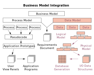
A data model is an abstract model that organizes elements of data and standardizes how they relate to one another and to the properties of real-world entities. For instance, a data model may specify that the data element representing a car be composed of a number of other elements which, in turn, represent the color and size of the car and define its owner.
An entity–relationship model describes interrelated things of interest in a specific domain of knowledge. A basic ER model is composed of entity types and specifies relationships that can exist between entities.
Data modeling in software engineering is the process of creating a data model for an information system by applying certain formal techniques.
The Zachman Framework is an enterprise ontology and is a fundamental structure for enterprise architecture which provides a formal and structured way of viewing and defining an enterprise. The ontology is a two dimensional classification schema that reflects the intersection between two historical classifications. The first are primitive interrogatives: What, How, When, Who, Where, and Why. The second is derived from the philosophical concept of reification, the transformation of an abstract idea into an instantiation. The Zachman Framework reification transformations are: identification, definition, representation, specification, configuration and instantiation.
A logical data model or logical schema is a data model of a specific problem domain expressed independently of a particular database management product or storage technology but in terms of data structures such as relational tables and columns, object-oriented classes, or XML tags. This is as opposed to a conceptual data model, which describes the semantics of an organization without reference to technology.
Database design is the organization of data according to a database model. The designer determines what data must be stored and how the data elements interrelate. With this information, they can begin to fit the data to the database model. A database management system manages the data accordingly.
The Department of Defense Architecture Framework (DoDAF) is an architecture framework for the United States Department of Defense (DoD) that provides visualization infrastructure for specific stakeholders concerns through viewpoints organized by various views. These views are artifacts for visualizing, understanding, and assimilating the broad scope and complexities of an architecture description through tabular, structural, behavioral, ontological, pictorial, temporal, graphical, probabilistic, or alternative conceptual means. The current release is DoDAF 2.02.
A conceptual model is a representation of a system. It consists of concepts used to help people know, understand, or simulate a subject the model represents. In contrast, a physical model focuses on a physical object such as a toy model that may be assembled and made to work like the object it represents.
Integration DEFinition for information modeling (IDEF1X) is a data modeling language for the development of semantic data models. IDEF1X is used to produce a graphical information model which represents the structure and semantics of information within an environment or system.
The British Ministry of Defence Architecture Framework (MODAF) was an architecture framework which defined a standardised way of conducting enterprise architecture, originally developed by the UK Ministry of Defence. It has since been replaced with the NATO Architecture Framework.
Object-oriented design (OOD) is the process of planning a system of interacting objects for the purpose of solving a software problem. It is one approach to software design.
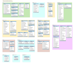
A database model is a type of data model that determines the logical structure of a database. It fundamentally determines in which manner data can be stored, organized and manipulated. The most popular example of a database model is the relational model, which uses a table-based format.
Entity Framework (EF) is an open source object–relational mapping (ORM) framework for ADO.NET. It was originally shipped as an integral part of .NET Framework, however starting with Entity Framework version 6.0 it has been delivered separately from the .NET Framework.
The three-schema approach, or three-schema concept, in software engineering is an approach to building information systems and systems information management that originated in the 1970s. It proposes three different views in systems development, with conceptual modelling being considered the key to achieving data integration.
A view model or viewpoints framework in systems engineering, software engineering, and enterprise engineering is a framework which defines a coherent set of views to be used in the construction of a system architecture, software architecture, or enterprise architecture. A view is a representation of the whole system from the perspective of a related set of concerns.
Operational View (OV) is one of the basic views defined in the enterprise architecture (EA) of the Department of Defense Architecture Framework V1.5 (DoDAF) and is related with concept of operations. Under DODAF 2, which became operational in 2009, the collections of views are now termed 'viewpoints' and no longer views.
Technical Architecture Framework for Information Management (TAFIM) was a 1990s reference model for enterprise architecture by and for the United States Department of Defense (DoD).
NIST Enterprise Architecture Model is a late-1980s reference model for enterprise architecture. It defines an enterprise architecture by the interrelationship between an enterprise's business, information, and technology environments.
The Lifecycle Modeling Language (LML) is an open-standard modeling language designed for systems engineering. It supports the full lifecycle: conceptual, utilization, support and retirement stages. Along with the integration of all lifecycle disciplines including, program management, systems and design engineering, verification and validation, deployment and maintenance into one framework. LML was originally designed by the LML steering committee. The specification was published October 17, 2013.