A lens is a transmissive optical device that focuses or disperses a light beam by means of refraction. A simple lens consists of a single piece of transparent material, while a compound lens consists of several simple lenses (elements), usually arranged along a common axis. Lenses are made from materials such as glass or plastic and are ground, polished, or molded to the required shape. A lens can focus light to form an image, unlike a prism, which refracts light without focusing. Devices that similarly focus or disperse waves and radiation other than visible light are also called "lenses", such as microwave lenses, electron lenses, acoustic lenses, or explosive lenses.

A flight simulator is a device that artificially re-creates aircraft flight and the environment in which it flies, for pilot training, design, or other purposes. It includes replicating the equations that govern how aircraft fly, how they react to applications of flight controls, the effects of other aircraft systems, and how the aircraft reacts to external factors such as air density, turbulence, wind shear, cloud, precipitation, etc. Flight simulation is used for a variety of reasons, including flight training, the design and development of the aircraft itself, and research into aircraft characteristics and control handling qualities.
The focal length of an optical system is a measure of how strongly the system converges or diverges light; it is the inverse of the system's optical power. A positive focal length indicates that a system converges light, while a negative focal length indicates that the system diverges light. A system with a shorter focal length bends the rays more sharply, bringing them to a focus in a shorter distance or diverging them more quickly. For the special case of a thin lens in air, a positive focal length is the distance over which initially collimated (parallel) rays are brought to a focus, or alternatively a negative focal length indicates how far in front of the lens a point source must be located to form a collimated beam. For more general optical systems, the focal length has no intuitive meaning; it is simply the inverse of the system's optical power.

A mirror image is a reflected duplication of an object that appears almost identical, but is reversed in the direction perpendicular to the mirror surface. As an optical effect, it results from specular reflection off from surfaces of lustrous materials, especially a mirror or water. It is also a concept in geometry and can be used as a conceptualization process for 3D structures.

Stereoscopy is a technique for creating or enhancing the illusion of depth in an image by means of stereopsis for binocular vision. The word stereoscopy derives from Greek στερεός (stereos) 'firm, solid', and σκοπέω (skopeō) 'to look, to see'. Any stereoscopic image is called a stereogram. Originally, stereogram referred to a pair of stereo images which could be viewed using a stereoscope.

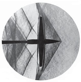
Schlieren photography is a process for photographing fluid flow. Invented by the German physicist August Toepler in 1864 to study supersonic motion, it is widely used in aeronautical engineering to photograph the flow of air around objects.

A collimated beam of light or other electromagnetic radiation has parallel rays, and therefore will spread minimally as it propagates. A laser beam is an archetypical example. A perfectly collimated light beam, with no divergence, would not disperse with distance. However, diffraction prevents the creation of any such beam.

A head-up display, or heads-up display, also known as a HUD or head-up guidance system (HGS), is any transparent display that presents data without requiring users to look away from their usual viewpoints. The origin of the name stems from a pilot being able to view information with the head positioned "up" and looking forward, instead of angled down looking at lower instruments. A HUD also has the advantage that the pilot's eyes do not need to refocus to view the outside after looking at the optically nearer instruments.

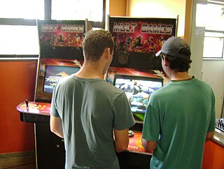
An arcade cabinet, also known as an arcade machine or a coin-op cabinet or coin-op machine, is the housing within which an arcade game's electronic hardware resides. Most cabinets designed since the mid-1980s conform to the Japanese Amusement Machine Manufacturers Association (JAMMA) wiring standard. Some include additional connectors for features not included in the standard.

In geometrical optics, a focus, also called an image point, is a point where light rays originating from a point on the object converge. Although the focus is conceptually a point, physically the focus has a spatial extent, called the blur circle. This non-ideal focusing may be caused by aberrations of the imaging optics. In the absence of significant aberrations, the smallest possible blur circle is the Airy disc, which is caused by diffraction from the optical system's aperture. Aberrations tend to worsen as the aperture diameter increases, while the Airy circle is smallest for large apertures.
A collimator is a device which narrows a beam of particles or waves. To narrow can mean either to cause the directions of motion to become more aligned in a specific direction, or to cause the spatial cross section of the beam to become smaller.

A head-mounted display (HMD) is a display device, worn on the head or as part of a helmet, that has a small display optic in front of one or each eye. HMDs have many uses including gaming, aviation, engineering, and medicine.

A synthetic vision system (SVS) is a computer-mediated reality system for aerial vehicles, that uses 3D to provide pilots with clear and intuitive means of understanding their flying environment.
Autocollimation is an optical setup where a collimated beam leaves an optical system and is reflected back into the same system by a plane mirror.

A curved mirror is a mirror with a curved reflecting surface. The surface may be either convex or concave. Most curved mirrors have surfaces that are shaped like part of a sphere, but other shapes are sometimes used in optical devices. The most common non-spherical type are parabolic reflectors, found in optical devices such as reflecting telescopes that need to image distant objects, since spherical mirror systems, like spherical lenses, suffer from spherical aberration. Distorting mirrors are used for entertainment. They have convex and concave regions that produce deliberately distorted images. They also provide highly magnified or highly diminished (smaller) images when the object is placed at certain distances.

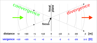
In optics, vergence is the angle formed by rays of light that are not perfectly parallel to one another. Rays that move closer to the optical axis as they propagate are said to be converging, while rays that move away from the axis are diverging. These imaginary rays are always perpendicular to the wavefront of the light, thus the vergence of the light is directly related to the radii of curvature of the wavefronts. A convex lens or concave mirror will cause parallel rays to focus, converging toward a point. Beyond that focal point, the rays diverge. Conversely, a concave lens or convex mirror will cause parallel rays to diverge.

Full flight simulator (FFS) is a term used by national (civil) aviation authorities (NAA) for a high technical level of flight simulator. Such authorities include the Federal Aviation Administration (FAA) in the United States and the European Aviation Safety Agency (EASA).

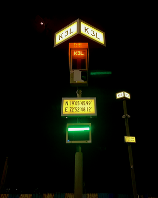
A stand guidance system is a system which gives information to a pilot attempting to park an aircraft at an airport stand, usually via visual methods, leading to the term Visual Docking Guidance System (VDGS) and also A-VDGS This allows them to remain clear of obstructions and ensures that jetways can reach the aircraft.

AXIS Flight Training Systems GmbH supplies EASA- and FAA-compliant flight training equipment, from flat panel trainers to full flight simulators. It was founded in 2004 in Graz/Austria. Their first design was a level D full flight simulator. In 2005 they produced a level D full flight simulator with an Equipe collimated visual system and a Rexroth hydraulic motion base.

X-ray computed tomography operates by using an X-ray generator that rotates around the object; X-ray detectors are positioned on the opposite side of the circle from the X-ray source.


