Current limiting is the practice of imposing a limit on the current that may be delivered to a load to protect the circuit generating or transmitting the current from harmful effects due to a short-circuit or overload. The term "current limiting" is also used to define a type of overcurrent protective device. According to the 2020 NEC/NFPA 70, a current-limiting overcurrent protective device is defined as, "A device that, when interrupting currents in its current-limiting range, reduces the current flowing in the faulted circuit to a magnitude substantially less than that obtainable in the same circuit if the device were replaced with a solid conductor having compatible impedance."
An inrush current limiter is a device or devices combination used to limit inrush current. Passive resistive components such as resistors (with power dissipation drawback), or negative temperature coefficient (NTC) thermistors are simple options while the positive one (PTC) is used to limit max current afterward as the circuit has been operating (with cool-down time drawback on both). More complex solutions using active components can be used when more straightforward options are unsuitable.
Some electronic circuits employ active current limiting since a fuse may not protect solid-state devices.
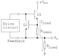
One style of current limiting circuit is shown in the image. The schematic represents a simple protection mechanism used in regulated DC supplies and class-AB power amplifiers.
Q1 is the pass or output transistor. Rsens is the load current sensing device. Q2 is the protection transistor which turns on as soon as the voltage across Rsens becomes about 0.65 V. This voltage is determined by the value of Rsens and the load current through it (Iload). When Q2 turns on, it removes the base current from Q1, thereby reducing the collector current of Q1, which is nearly the load current. Thus, Rsens fixes the maximum current to a value given by 0.65/Rsens. For example, if Rsens = 0.33 Ω, the current is limited to about 2 A even if Rload becomes a short (and Vo becomes zero).
Further, this power dissipation will remain as long as the overload exists, which means that the devices must be capable of withstanding it for a substantial period. This power dissipation will be substantially less than if no current limiting circuit had been provided. In this technique, beyond the current limit, the output voltage will decrease to a value depending on the current limit and load resistance.
To reduce the heat that must be dissipated by the pass devices under a short-circuit, foldback current limiting is used, which reduces current in the short-circuit case. Under a short circuit, where the output voltage has reduced to zero, the current is typically limited to a small fraction of the maximum current.
The prime purpose of foldback current limiting in linear power supplies is to keep the output transistor within its safe power dissipation limit. A linear regulator dissipates the difference between input and output voltages as heat. Under overload conditions, the output voltage falls, so the difference becomes larger, thus increasing dissipation. Foldback helps to keep the output transistor within its safe operating area under fault and overload conditions. Foldback also significantly reduces the power dissipation in the load in fault conditions, which can reduce the risks of fire and heat damage. [1]
Many power supplies employ constant current limiting protection; foldback goes one step further by linearly reducing the output current limit as output voltage decreases. However, it adds complexity to the power supply. It can trigger "lockout" conditions with non-ohmic devices that draw a constant current independent of the supply voltage (such as op-amps). A foldback current limiter may also employ a transient delay to avoid lockout and limit localized heating at the short circuit.
A switched-mode power supply operating at the current limit with the output short-circuited does not have increased power dissipation in the power transistor(s), so foldback current limiting is an application feature only rather than one that also prevents a load fault from also destroying the power supply. The safety benefit of reducing the power delivered to a short circuit in the load is proportional to the operating current limit. Foldback current limiting is most likely to be found in a switch-mode power supply when it is a component in a product that is independently certified to meet regional safety standards. [2]
An issue with the previous circuit is that Q1 will not be saturated unless its base is biased about 0.5 volts above Vcc.
These circuits operate more efficiently from a single (Vcc) supply. In both circuits, R1 allows Q1 to turn on and pass voltage and current to the load. When the current through R_sense exceeds the design limit, Q2 turns on, which in turn begins to turn off Q1, thus limiting the load current. The optional component R2 protects Q2 in the event of a short-circuited load. When Vcc is at least a few volts, a MOSFET can be used for Q1 for lower dropout voltage. Due to its simplicity, this circuit is sometimes used as a current source for high-power LEDs. [3]
An amplifier, electronic amplifier or (informally) amp is an electronic device that can increase the magnitude of a signal. It is a two-port electronic circuit that uses electric power from a power supply to increase the amplitude of a signal applied to its input terminals, producing a proportionally greater amplitude signal at its output. The amount of amplification provided by an amplifier is measured by its gain: the ratio of output voltage, current, or power to input. An amplifier is defined as a circuit that has a power gain greater than one.
A multivibrator is an electronic circuit used to implement a variety of simple two-state devices such as relaxation oscillators, timers, latches and flip-flops. The first multivibrator circuit, the astable multivibrator oscillator, was invented by Henri Abraham and Eugene Bloch during World War I. It consisted of two vacuum tube amplifiers cross-coupled by a resistor-capacitor network. They called their circuit a "multivibrator" because its output waveform was rich in harmonics. A variety of active devices can be used to implement multivibrators that produce similar harmonic-rich wave forms; these include transistors, neon lamps, tunnel diodes and others. Although cross-coupled devices are a common form, single-element multivibrator oscillators are also common.
An operational amplifier is a DC-coupled high-gain electronic voltage amplifier with a differential input and, usually, a single-ended output. In this configuration, an op amp produces an output potential that is typically 100,000 times larger than the potential difference between its input terminals. The operational amplifier traces its origin and name to analog computers, where they were used to perform mathematical operations in linear, non-linear, and frequency-dependent circuits.
Transistor–transistor logic (TTL) is a logic family built from bipolar junction transistors. Its name signifies that transistors perform both the logic function and the amplifying function, as opposed to earlier resistor–transistor logic (RTL) and diode–transistor logic (DTL).
A power supply is an electrical device that supplies electric power to an electrical load. The main purpose of a power supply is to convert electric current from a source to the correct voltage, current, and frequency to power the load. As a result, power supplies are sometimes referred to as electric power converters. Some power supplies are separate standalone pieces of equipment, while others are built into the load appliances that they power. Examples of the latter include power supplies found in desktop computers and consumer electronics devices. Other functions that power supplies may perform include limiting the current drawn by the load to safe levels, shutting off the current in the event of an electrical fault, power conditioning to prevent electronic noise or voltage surges on the input from reaching the load, power-factor correction, and storing energy so it can continue to power the load in the event of a temporary interruption in the source power.
In electronics, a linear regulator is a voltage regulator used to maintain a steady voltage. The resistance of the regulator varies in accordance with both the input voltage and the load, resulting in a constant voltage output. The regulating circuit varies its resistance, continuously adjusting a voltage divider network to maintain a constant output voltage and continually dissipating the difference between the input and regulated voltages as waste heat. By contrast, a switching regulator uses an active device that switches on and off to maintain an average value of output. Because the regulated voltage of a linear regulator must always be lower than input voltage, efficiency is limited and the input voltage must be high enough to always allow the active device to reduce the voltage by some amount.
In electronics, a Schmitt trigger is a comparator circuit with hysteresis implemented by applying positive feedback to the noninverting input of a comparator or differential amplifier. It is an active circuit which converts an analog input signal to a digital output signal. The circuit is named a trigger because the output retains its value until the input changes sufficiently to trigger a change. In the non-inverting configuration, when the input is higher than a chosen threshold, the output is high. When the input is below a different (lower) chosen threshold the output is low, and when the input is between the two levels the output retains its value. This dual threshold action is called hysteresis and implies that the Schmitt trigger possesses memory and can act as a bistable multivibrator. There is a close relation between the two kinds of circuits: a Schmitt trigger can be converted into a latch and a latch can be converted into a Schmitt trigger.
A current mirror is a circuit designed to copy a current through one active device by controlling the current in another active device of a circuit, keeping the output current constant regardless of loading. The current being "copied" can be, and sometimes is, a varying signal current. Conceptually, an ideal current mirror is simply an ideal inverting current amplifier that reverses the current direction as well, or it could consist of a current-controlled current source (CCCS). The current mirror is used to provide bias currents and active loads to circuits. It can also be used to model a more realistic current source.
A voltage regulator is a system designed to automatically maintain a constant voltage. It may use a simple feed-forward design or may include negative feedback. It may use an electromechanical mechanism, or electronic components. Depending on the design, it may be used to regulate one or more AC or DC voltages.
A motor controller is a device or group of devices that can coordinate in a predetermined manner the performance of an electric motor. A motor controller might include a manual or automatic means for starting and stopping the motor, selecting forward or reverse rotation, selecting and regulating the speed, regulating or limiting the torque, and protecting against overloads and electrical faults. Motor controllers may use electromechanical switching, or may use power electronics devices to regulate the speed and direction of a motor.
A current source is an electronic circuit that delivers or absorbs an electric current which is independent of the voltage across it.
A push–pull amplifier is a type of electronic circuit that uses a pair of active devices that alternately supply current to, or absorb current from, a connected load. This kind of amplifier can enhance both the load capacity and switching speed.
For power semiconductor devices, the safe operating area (SOA) is defined as the voltage and current conditions over which the device can be expected to operate without self-damage.
Inrush current, input surge current, or switch-on surge is the maximal instantaneous input current drawn by an electrical device when first turned on. Alternating-current electric motors and transformers may draw several times their normal full-load current when first energized, for a few cycles of the input waveform. Power converters also often have inrush currents much higher than their steady-state currents, due to the charging current of the input capacitance. The selection of over-current-protection devices such as fuses and circuit breakers is made more complicated when high inrush currents must be tolerated. The over-current protection must react quickly to overload or short-circuit faults but must not interrupt the circuit when the inrush current flows.
A Wilson current mirror is a three-terminal circuit that accepts an input current at the input terminal and provides a "mirrored" current source or sink output at the output terminal. The mirrored current is a precise copy of the input current. It may be used as a Wilson current source by applying a constant bias current to the input branch as in Fig. 2. The circuit is named after George R. Wilson, an integrated circuit design engineer who worked for Tektronix. Wilson devised this configuration in 1967 when he and Barrie Gilbert challenged each other to find an improved current mirror overnight that would use only three transistors. Wilson won the challenge.
Supervisory circuits are electronic circuits that monitor one or more parameters of systems such as power supplies and microprocessors which must be maintained within certain limits, and take appropriate action if a parameter goes out of bounds, creating an unacceptable or dangerous situation.
An active load or dynamic load is a component or a circuit that functions as a current-stable nonlinear resistor.
Bipolar transistors must be properly biased to operate correctly. In circuits made with individual devices, biasing networks consisting of resistors are commonly employed. Much more elaborate biasing arrangements are used in integrated circuits, for example, bandgap voltage references and current mirrors. The voltage divider configuration achieves the correct voltages by the use of resistors in certain patterns. By selecting the proper resistor values, stable current levels can be achieved that vary only little over temperature and with transistor properties such as β.
In an electric power system, overcurrent or excess current is a situation where a larger than intended electric current exists through a conductor, leading to excessive generation of heat, and the risk of fire or damage to equipment. Possible causes for overcurrent include short circuits, excessive load, incorrect design, an arc fault, or a ground fault. Fuses, circuit breakers, and current limiters are commonly used overcurrent protection (OCP) mechanisms to control the risks. Circuit breakers, relays, and fuses protect circuit wiring from damage caused by overcurrent.
A joule thief is a minimalist self-oscillating voltage booster that is small, low-cost, and easy to build, typically used for driving small loads, such as driving an LED using a 1.5 volt battery. This circuit is also known by other names such as blocking oscillator, joule ringer, or vampire torch. It can use nearly all of the energy in a single-cell electric battery, even far below the voltage where other circuits consider the battery fully discharged ; hence the name, which suggests the notion that the circuit is stealing energy or "joules" from the source – the term is a pun on "jewel thief". The circuit is a variant of the blocking oscillator that forms an unregulated voltage boost converter.