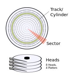
It is a 3D-coordinate system made out of a vertical coordinate head, a horizontal (or radial) coordinate cylinder, and an angular coordinate sector. Head selects a circular surface: a platter in the disk (and one of its two sides). Cylinder is a cylindrical intersection through the stack of platters in a disk, centered around the disk's spindle. Combined, cylinder and head intersect to a circular line, or more precisely: a circular strip of physical data blocks called track. Sector finally selects which data block in this track is to be addressed, as the track is subdivided into several equally-sized portions, each of which is an arc of (360/n) degrees, where n is the number of sectors in the track.
CHS addresses were exposed, instead of simple linear addresses (going from 0 to the total block count on disk - 1), because early hard drives didn't come with an embedded disk controller, that would hide the physical layout. A separate generic controller card was used, so that the operating system had to know the exact physical "geometry" of the specific drive attached to the controller, to correctly address data blocks. The traditional limits were 512 bytes/sector × 63 sectors/track × 255 heads (tracks/cylinder) × 1024 cylinders, resulting in a limit of 8032.5 MiB for the total capacity of a disk.
As the geometry became more complicated (for example, with the introduction of zone bit recording) and drive sizes grew over time, the CHS addressing method became restrictive. Since the late 1980s, hard drives began shipping with an embedded disk controller[1] that had good knowledge of the physical geometry; they would however report a false geometry to the computer, e.g., a larger number of heads than actually present, to gain more addressable space. These logical CHS values would be translated by the controller, thus CHS addressing no longer corresponded to any physical attributes of the drive.[2]
By the mid 1990s, hard drive interfaces replaced the CHS scheme with logical block addressing (LBA), but many tools for manipulating the master boot record (MBR) partition table still aligned partitions to cylinder boundaries; thus, artifacts of CHS addressing were still seen in partitioning software by the late 2000s.[2]
In the early 2010s, the disk size limitations imposed by MBR became problematic and the GUID Partition Table (GPT) was designed as a replacement; modern computers using UEFI firmware without MBR support no longer use any notions from CHS addressing.
Definitions
schematic of the hard drive geometry
CHS addressing is the process of identifying individual sectors (aka. physical block of data) on a disk by their position in a track, where the track is determined by the head and cylinder numbers. The terms are explained bottom up, for disk addressing the sector is the smallest unit. Disk controllers can introduce address translations to map logical to physical positions, e.g., zone bit recording stores fewer sectors in shorter (inner) tracks, physical disk formats are not necessarily cylindrical, and sector numbers in a track can be skewed.
Sectors
Floppy disks and controllers had used physical sector sizes of 128, 256, 512 and 1024 bytes (e.g., PC/AX), but formats with 512 bytes per physical sector became dominant in the 1980s.[3][4]
The most common physical sector size for hard disks today is 512 bytes, but there have been hard disks with 520 bytes per sector as well for non-IBM compatible machines. In 2005 some Seagate custom hard disks used sector sizes of 1024 bytes per sector.[citation needed]
Advanced Format hard disks use 4096 bytes per physical sector (4Kn)[5] since 2010, but will also be able to emulate 512 byte sectors (512e) for a transitional period.[6]
Magneto-optical drives use sector sizes of 512 and 1024 bytes on 5.25-inch drives and 512 and 2048 bytes on 3.5-inch drives.
In CHS addressing the sector numbers always start at 1; there is no sector 0.
For physical disk geometries the maximal sector number is determined by the low level format of the disk. However, for disk access with the BIOS of IBM PC compatible machines, the sector number was encoded in six bits, resulting in a maximal number of 111111 (63) sectors per track. This maximum is still in use for virtual CHS geometries.
Tracks
The tracks are the thin concentric circular strips of sectors. At least one head is required to read a single track. With respect to disk geometries the terms track and cylinder are closely related. For a single or double sided floppy disktrack is the common term; and for more than two heads cylinder is the common term. Strictly speaking a track is a given CH combination consisting ofSPT sectors, while a cylinder consists ofSPT×H sectors.
Cylinders
A cylinder is a division of data in a disk drive, as used in the CHS addressing mode of a fixed-block architecture (FBA) disk or the cylinder–head–record (CCHHR) addressing mode of a CKD disk.
The concept is concentric, hollow, cylindrical slices through the physical disks (platters), collecting the respective circular tracks aligned through the stack of platters. The number of cylinders of a disk drive exactly equals the number of tracks on a single surface in the drive. It comprises the same track number on each platter, spanning all such tracks across each platter surface that is able to store data (without regard to whether or not the track is "bad"). Cylinders are vertically formed by tracks. In other words, track 12 on platter 0 plus track 12 on platter 1 etc. is cylinder 12.
Other forms of Direct Access Storage Device (DASD), such as drum memory devices or the IBM 2321 Data Cell, might give blocks addresses that include a cylinder address, although the cylinder address doesn't select a (geometric) cylindrical slice of the device.
Heads
A device called a head reads and writes data in a hard drive by manipulating the magnetic medium that composes the surface of an associated disk platter. Naturally, a platter has 2 sides and thus 2 surfaces on which data can be manipulated; usually there are 2 heads per platter, one per side. (Sometimes the term side is substituted for head, since platters might be separated from their head assemblies, as with the removable media of a floppy drive.)
The CHS addressing supported in IBM-PC compatible BIOSes code used eight bits for a maximum of 256 heads counted as head 0 up to 255 (FFh). However, a bug in all versions of MS-DOS / IBM PC DOS up to and including 7.10 will cause these operating systems to crash on boot when encountering volumes with 256 heads. Therefore, all compatible BIOSes will use mappings with up to 255 heads (00h..FEh) only, including in virtual 255×63 geometries. This historical oddity can affect the maximum disk size:
(512 bytes/sector)×(63 sectors/track)×(255 heads (tracks/cylinder))×(1024 cylinders)=8032.5MiB, but actually 512×63×256×1024=8064MiB yields what is known as 8GB limit.[7] In this context relevant definition of 8GiB = 8192MiB is another incorrect limit, because it would require CHS 512×64×256 with 64 sectors per track.
Tracks and cylinders are counted from 0, i.e., track 0 is the first (outer-most) track on floppy or other cylindrical disks. Old BIOS code supported ten bits in CHS addressing with up to 1024 cylinders (1024=210). Adding six bits for sectors and eight bits for heads results in the 24 bits supported by BIOS interrupt 13h. Subtracting the disallowed sector number 0 in 1024×256 tracks corresponds to 128MiB for a sector size of 512 bytes (128MiB=1024×256×(512 byte/sector)); and 8192-128=8064 confirms the (roughly) 8GB limit.[8]
CHS addressing starts at 0/0/1 with a maximal value 1023/255/63 for 24=10+8+6 bits, or 1023/254/63 for 24 bits limited to 255 heads. CHS values used to specify the geometry of a disk have to count cylinder 0 and head 0 resulting in a maximum (1024/256/63 or) 1024/255/63 for 24 bits with (256 or) 255 heads. In CHS tuples specifying a geometry S actually means sectors per track, and where the (virtual) geometry still matches the capacity the disk contains C×H×S sectors. As larger hard disks have come into use, a cylinder has become also a logical disk structure, standardised[citation needed] at 16065 sectors (16065=255×63).
CHS addressing with 28 bits (EIDE and ATA-2) permits eight bits for sectors still starting at 1, i.e., sectors 1...255, four bits for heads 0...15, and sixteen bits for cylinders 0...65535.[9] This results in a roughly 128GB limit; actually 65536×16×255=267386880 sectors corresponding to 130560MiB for a sector size of 512 bytes.[7] The 28=16+4+8 bits in the ATA-2 specification are also covered by Ralf Brown's Interrupt List, and an old working draft of this now expired standard was published.[10]
With an old BIOS limit of 1024 cylinders and the ATA limit of 16 heads[11] the combined effect was 1024×16×63=1032192 sectors, i.e., a 504MiB limit for sector size 512. BIOS translation schemes known as ECHS and revised ECHS mitigated this limitation by using 128 or 240 instead of 16 heads, simultaneously reducing the numbers of cylinders and sectors to fit into 1024/128/63 (ECHS limit: 4032MiB) or 1024/240/63 (revised ECHS limit: 7560MiB) for the given total number of sectors on a disk.[7]
Blocks and clusters
The Unix communities employ the term block to refer to a sector or group of sectors. For example, the Linux fdisk utility, before version 2.25,[12] displayed partition sizes using 1024-byte blocks.
Clusters are allocation units for data on various file systems (FAT, NTFS, etc.), where data mainly consists of files. Clusters are not directly affected by the physical or virtual geometry of the disk, i.e., a cluster can begin at a sector near the end of a given CH track, and end in a sector on the physically or logically next CHtrack.
In 2002 the ATA-6 specification introduced an optional 48 bits Logical Block Addressing and declared CHS addressing as obsolete, but still allowed to implement the ATA-5 translations.[13] Unsurprisingly the CHS to LBA translation formula given below also matches the last ATA-5 CHS translation. In the ATA-5 specification CHS support was mandatory for up to 16514064 sectors and optional for larger disks. The ATA-5 limit corresponds to CHS 16383 16 63 or equivalent disk capacities (16514064 = 16383 × 16 × 63= 1032 × 254 × 63), and requires 24 = 14 + 4 + 6 bits (16383 + 1 = 214).[14]
CHS tuples can be mapped onto LBA addresses using the following formula:
where A is the LBA address, Nheads is the number of heads on the disk, Nsectors is the maximum number of sectors per track, and (c, h, s) is the CHS address.
A Logical Sector Number formula in the ECMA-107[3] and ISO/IEC9293:1994[15] (superseding ISO9293:1987[16]) standards for FAT file systems matches exactly the LBA formula given above: Logical Block Address and Logical Sector Number (LSN) are synonyms.[3][15][16] The formula does not use the number of cylinders, but requires the number of heads and the number of sectors per track in the disk geometry, because the same CHS tuple addresses different logical sector numbers depending on the geometry.
Examples:
For geometry 1020 16 63 of a disk with 1028160 sectors, CHS 3 2 1 is LBA 3150 = ((3 × 16) + 2) × 63 + (1 – 1);
For geometry 1008 4 255 of a disk with 1028160 sectors, CHS 3 2 1 is LBA 3570 = ((3 × 4) + 2) × 255 + (1 – 1)
For geometry 64 255 63 of a disk with 1028160 sectors, CHS 3 2 1 is LBA 48321=((3 × 255) + 2) × 63 + (1 – 1)
For geometry 2142 15 32 of a disk with 1028160 sectors, CHS 3 2 1 is LBA 1504 = ((3 × 15) + 2) × 32 + (1 – 1)
To help visualize the sequencing of sectors into a linear LBA model, note that:
The first LBA sector is sector # zero, the same sector in a CHS model is called sector # one.
All the sectors of each head/track get counted before incrementing to the next head/track.
All the heads/tracks of the same cylinder get counted before incrementing to the next cylinder.
The outside half of a whole hard drive would be the first half of the drive.
History
Cylinder Head Record format has been used by Count Key Data (CKD) hard disks on IBM mainframes since at least the 1960s. This is largely comparable to the Cylinder Head Sector format used by PCs, with the exception that the sector size was not fixed but could vary from track to track based on the needs of each application. In contemporary use, the disk geometry presented to the mainframe is emulated by the storage firmware, and no longer has any relation to physical disk geometry.[citation needed]
Earlier hard drives used in the PC, such as MFM and RLL drives, divided each cylinder into an equal number of sectors, so the CHS values matched the physical properties of the drive. A drive with a CHS tuple of 500 4 32 would have 500 tracks per side on each platter, two platters (4 heads), and 32 sectors per track, with a total of 32768000 bytes (31.25MiB).[citation needed]
ATA/IDE drives were much more efficient at storing data and have replaced the now-obsolete MFM and RLL drives. They use zone bit recording (ZBR), where the number of sectors dividing each track varies with the location of groups of tracks on the surface of the platter. Tracks nearer to the edge of the platter contain more blocks of data than tracks close to the spindle, because there is more physical space within a given track near the edge of the platter. Thus, the CHS addressing scheme cannot correspond directly with the physical geometry of such drives, due to the varying number of sectors per track for different regions on a platter. Because of this, many drives still have a surplus of sectors (less than 1 cylinder in size) at the end of the drive, since the total number of sectors rarely, if ever, ends on a cylinder boundary.[citation needed]
An ATA/IDE drive can be set in the system BIOS with any configuration of cylinders, heads and sectors that do not exceed the capacity of the drive (or the BIOS), since the drive will convert any given CHS value into an actual address for its specific hardware configuration. This however can cause compatibility problems.[citation needed]
For operating systems such as MicrosoftDOS or older version of Windows, each partition must start and end at a cylinder boundary.[citation needed] Only some of the relatively modern operating systems (Windows XP included) may disregard this rule, but doing so can still cause some compatibility issues, especially if the user wants to perform dual booting on the same drive. Microsoft does not follow this rule with internal disk partition tools since Windows Vista.[17]
↑ "ATA-6"(PDF). T13/1410D. INCITS Technical Committee T13 ATA Storage Interface. 2002. p.22. Archived from the original(PDF) on 28 July 2011. Retrieved 30 July 2011. In standards ATA/ATAPI-5 and earlier, a CHS translation was defined. This translation is obsolete but may be implemented as defined in ATA/ATAPI-5.
↑ "ATA-5"(PDF). T13/1321D. INCITS Technical Committee T13 ATA Storage Interface. 2000. p.19. Archived from the original(PDF) on 28 July 2011. Retrieved 30 July 2011. If the device's capacity is greater than or equal to one sector and less than or equal to 16,514,064 sectors, then the device shall support CHS translation.
1.^This rule is true at least for all formats where the physical sectors are named 1 upwards. However, there are a few odd floppy formats (e.g., the 640KB format used by BBC Master 512 with DOS Plus 2.1), where the first sector in a track is named "0" not "1".
2.^While computers begin counting at 0, DOS would begin counting at 1. In order to do this, DOS would add a 1 to the head count before displaying it on the screen. However, instead of converting the 8-bit unsigned integer to a larger size (such as a 16-bit integer) first, DOS just added the 1. This would overflow a head count of 255 (0xFF) into 0 (0x100 & 0xFF = 0x00) instead of the 256 that would be expected. This was fixed with DOS 8, but by then, it had become a de facto standard to not use a head value of 255.
This page is based on this Wikipedia article Text is available under the CC BY-SA 4.0 license; additional terms may apply. Images, videos and audio are available under their respective licenses.