
In aeronautics, the chord is an imaginary straight line segment joining the leading edge and trailing edge of an aerofoil cross section parallel to the direction of the airflow. The chord length is the distance between the trailing edge and the leading edge. The point on the leading edge used to define the main chord may be the surface point of minimum radius. For a turbine aerofoil, the chord may be defined by the line between points where the front and rear of a 2-dimensional blade section would touch a flat surface when laid convex-side up.

A tailplane, also known as a horizontal stabilizer, is a small lifting surface located on the tail (empennage) behind the main lifting surfaces of a fixed-wing aircraft as well as other non-fixed-wing aircraft such as helicopters and gyroplanes. Not all fixed-wing aircraft have tailplanes. Canards, tailless and flying wing aircraft have no separate tailplane, while in V-tail aircraft the vertical stabilizer, rudder, and the tail-plane and elevator are combined to form two diagonal surfaces in a V layout.

Flight dynamics is the science of air vehicle orientation and control in three dimensions. The three critical flight dynamics parameters are the angles of rotation in three dimensions about the vehicle's center of gravity (cg), known as pitch, roll and yaw. These are collectively known as aircraft attitude, often principally relative to the atmospheric frame in normal flight, but also relative to terrain during takeoff or landing, or when operating at low elevation. The concept of attitude is not specific to fixed-wing aircraft, but also extends to rotary aircraft such as helicopters, and dirigibles, where the flight dynamics involved in establishing and controlling attitude are entirely different.
In fluid dynamics, angle of attack is the angle between a reference line on a body and the vector representing the relative motion between the body and the fluid through which it is moving. Angle of attack is the angle between the body's reference line and the oncoming flow. This article focuses on the most common application, the angle of attack of a wing or airfoil moving through air.
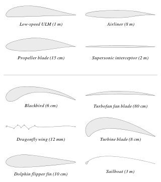
An airfoil or aerofoil is a streamlined body that is capable of generating significantly more lift than drag. Wings, sails and propeller blades are examples of airfoils. Foils of similar function designed with water as the working fluid are called hydrofoils.

Dihedral angle is the upward angle from horizontal of the wings or tailplane of a fixed-wing aircraft. "Anhedral angle" is the name given to negative dihedral angle, that is, when there is a downward angle from horizontal of the wings or tailplane of a fixed-wing aircraft.
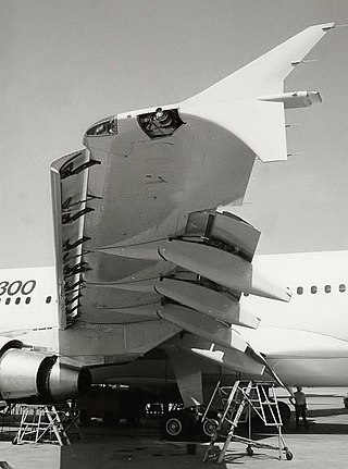
A flap is a high-lift device used to reduce the stalling speed of an aircraft wing at a given weight. Flaps are usually mounted on the wing trailing edges of a fixed-wing aircraft. Flaps are used to reduce the take-off distance and the landing distance. Flaps also cause an increase in drag so they are retracted when not needed.
Aircraft flight mechanics are relevant to fixed wing and rotary wing (helicopters) aircraft. An aeroplane, is defined in ICAO Document 9110 as, "a power-driven heavier than air aircraft, deriving its lift chiefly from aerodynamic reactions on surface which remain fixed under given conditions of flight".
A vertical stabilizer or tail fin is the static part of the vertical tail of an aircraft. The term is commonly applied to the assembly of both this fixed surface and one or more movable rudders hinged to it. Their role is to provide control, stability and trim in yaw. It is part of the aircraft empennage, specifically of its stabilizers.

An aircraft stabilizer is an aerodynamic surface, typically including one or more movable control surfaces, that provides longitudinal (pitch) and/or directional (yaw) stability and control. A stabilizer can feature a fixed or adjustable structure on which any movable control surfaces are hinged, or it can itself be a fully movable surface such as a stabilator. Depending on the context, "stabilizer" may sometimes describe only the front part of the overall surface.
In aeronautics and aeronautical engineering, camber is the asymmetry between the two acting surfaces of an airfoil, with the top surface of a wing commonly being more convex. An airfoil that is not cambered is called a symmetric airfoil. The benefits of cambering were discovered and first utilized by George Cayley in the early 19th century.

In aeronautics, a tailless aircraft is a fixed-wing aircraft with no other horizontal aerodynamic surface besides its main wing. It may still have a fuselage, vertical tail fin, and/or vertical rudder.
In flight dynamics, longitudinal stability is the stability of an aircraft in the longitudinal, or pitching, plane. This characteristic is important in determining whether an aircraft pilot will be able to control the aircraft in the pitching plane without requiring excessive attention or excessive strength.

In aviation, stagger is the relative horizontal fore-aft positioning of stacked wings in a biplane, triplane, or multiplane.

The wing configuration or planform of a fixed-wing aircraft is its arrangement of lifting and related surfaces.
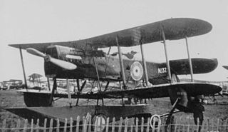
The Parnall Puffin was an experimental amphibious fighter-reconnaissance biplane produced in the United Kingdom just after World War I. It had several unusual features, principally a single central float and an inverted vertical stabilizer and rudder, and showed promise, but at that time no new aircraft were being ordered in numbers for the RAF and only the three Puffins of the initial order were built.
The Parnall Parasol was an experimental parasol winged aircraft design to measure the aerodynamic forces on wings in flight. Two were built and flown in the early 1930s in the UK.

The Mauboussin M.40 Hémiptère was an experimental, single seat, single engine light aircraft with unequal span tandem wings, designed in France in the 1930s. Only one was built.

The Feiro Dongó was a Hungarian side-by-side trainer biplane. It was notable for its high aspect ratio wings, aerodynamic clearness and high lift/drag ratio.

On fixed-wing aircraft, the angle of incidence is the angle between the chord line of the wing where the wing is mounted to the fuselage, and a reference axis along the fuselage. The angle of incidence is fixed in the design of the aircraft, and with rare exceptions, cannot be varied in flight.


