Related Research Articles

Amplitude modulation (AM) is a modulation technique used in electronic communication, most commonly for transmitting information via a radio carrier wave. In amplitude modulation, the amplitude of the carrier wave is varied in proportion to that of the message signal being transmitted. The message signal is, for example, a function of the sound to be reproduced by a loudspeaker, or the light intensity of pixels of a television screen. This technique contrasts with frequency modulation, in which the frequency of the carrier signal is varied, and phase modulation, in which its phase is varied.
Quadrature amplitude modulation (QAM) is the name of a family of digital modulation methods and a related family of analog modulation methods widely used in modern telecommunications to transmit information. It conveys two analog message signals, or two digital bit streams, by changing (modulating) the amplitudes of two carrier waves, using the amplitude-shift keying (ASK) digital modulation scheme or amplitude modulation (AM) analog modulation scheme. The two carrier waves of the same frequency are out of phase with each other by 90°, a condition known as orthogonality and as quadrature. Being the same frequency, the modulated carriers add together, but can be coherently separated (demodulated) because of their orthogonality property. Another key property is that the modulations are low-frequency/low-bandwidth waveforms compared to the carrier frequency, which is known as the narrowband assumption.

In radio communications, single-sideband modulation (SSB) or single-sideband suppressed-carrier modulation (SSB-SC) is a type of modulation, used to transmit information, such as an audio signal, by radio waves. A refinement of amplitude modulation, it uses transmitter power and bandwidth more efficiently. Amplitude modulation produces an output signal the bandwidth of which is twice the maximum frequency of the original baseband signal. Single-sideband modulation avoids this bandwidth increase, and the power wasted on a carrier, at the cost of increased device complexity and more difficult tuning at the receiver.
In telecommunication, data signaling rate (DSR), also known as gross bit rate, is the aggregate rate at which data pass a point in the transmission path of a data transmission system.
- The DSR is usually expressed in bits per second.
- The data signaling rate is given by where m is the number of parallel channels, ni is the number of significant conditions of the modulation in the i-th channel, and Ti is the unit interval, expressed in seconds, for the i-th channel.
- For serial transmission in a single channel, the DSR reduces to (1/T)log2n; with a two-condition modulation, i. e. n = 2, the DSR is 1/T, according to Hartley's law.
- For parallel transmission with equal unit intervals and equal numbers of significant conditions on each channel, the DSR is (m/T)log2n; in the case of a two-condition modulation, this reduces to m/T.
- The DSR may be expressed in bauds, in which case, the factor log2ni in the above summation formula should be deleted when calculating bauds.
- In synchronous binary signaling, the DSR in bits per second may be numerically the same as the modulation rate expressed in bauds. Signal processors, such as four-phase modems, cannot change the DSR, but the modulation rate depends on the line modulation scheme, in accordance with Note 4. For example, in a 2400 bit/s 4-phase sending modem, the signaling rate is 2400 bit/s on the serial input side, but the modulation rate is only 1200 bauds on the 4-phase output side.
In telecommunication, the term degree of start-stop distortion has the following meanings:
- In asynchronous serial communication data transmission, the ratio of (a) the absolute value of the maximum measured difference between the actual and theoretical intervals separating any significant instant of modulation from the significant instant of the start element immediately preceding it to (b) the unit interval.
- The highest absolute value of individual distortion affecting the significant instants of a start-stop modulation.
Distortion is the alteration of the original shape of something. In communications and electronics it means the alteration of the waveform of an information-bearing signal, such as an audio signal representing sound or a video signal representing images, in an electronic device or communication channel.
Double-sideband suppressed-carrier transmission (DSB-SC) is transmission in which frequencies produced by amplitude modulation (AM) are symmetrically spaced above and below the carrier frequency and the carrier level is reduced to the lowest practical level, ideally being completely suppressed.

Typically, prior to some process, such as transmission over cable, or recording to phonograph record or tape, the input frequency range most susceptible to noise is boosted. This is referred to as "pre-emphasis" – "pre-" the process the signal will undergo. Later, when the signal is received, or retrieved from recording, the reverse transformation is applied ("de-emphasis") so that the output accurately reproduces the original input. Any noise added by transmission or record/playback, to the frequency range previously boosted, is now attenuated in the de-emphasis stage.
Reduced-carrier transmission is an amplitude modulation (AM) transmission in which the carrier signal level is reduced to reduce wasted electrical power. Suppressed-carrier transmission is a special case in which the carrier level is reduced below that required for demodulation by a normal receiver.

Pulse-width modulation (PWM), or pulse-duration modulation (PDM), is a method of reducing the average power delivered by an electrical signal, by effectively chopping it up into discrete parts. The average value of voltage fed to the load is controlled by turning the switch between supply and load on and off at a fast rate. The longer the switch is on compared to the off periods, the higher the total power supplied to the load. Along with MPPT maximum power point tracking, it is one of the primary methods of reducing the output of solar panels to that which can be utilized by a battery. PWM is particularly suited for running inertial loads such as motors, which are not as easily affected by this discrete switching. Because they have inertia they react slower. The PWM switching frequency has to be high enough not to affect the load, which is to say that the resultant waveform perceived by the load must be as smooth as possible.
A satellite modem or satmodem is a modem used to establish data transfers using a communications satellite as a relay. A satellite modem's main function is to transform an input bitstream to a radio signal and vice versa.
Continuous phase modulation (CPM) is a method for modulation of data commonly used in wireless modems. In contrast to other coherent digital phase modulation techniques where the carrier phase abruptly resets to zero at the start of every symbol, with CPM the carrier phase is modulated in a continuous manner. For instance, with QPSK the carrier instantaneously jumps from a sine to a cosine whenever one of the two message bits of the current symbol differs from the two message bits of the previous symbol. This discontinuity requires a relatively large percentage of the power to occur outside of the intended band, leading to poor spectral efficiency. Furthermore, CPM is typically implemented as a constant-envelope waveform, i.e., the transmitted carrier power is constant. Therefore, CPM is attractive because the phase continuity yields high spectral efficiency, and the constant envelope yields excellent power efficiency. The primary drawback is the high implementation complexity required for an optimal receiver.
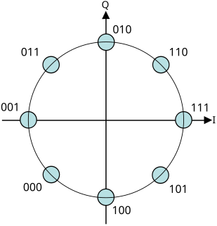
A constellation diagram is a representation of a signal modulated by a digital modulation scheme such as quadrature amplitude modulation or phase-shift keying. It displays the signal as a two-dimensional xy-plane scatter diagram in the complex plane at symbol sampling instants. The angle of a point, measured counterclockwise from the horizontal axis, represents the phase shift of the carrier wave from a reference phase. The distance of a point from the origin represents a measure of the amplitude or power of the signal.

In radio, a detector is a device or circuit that extracts information from a modulated radio frequency current or voltage. The term dates from the first three decades of radio (1888-1918). Unlike modern radio stations which transmit sound on an uninterrupted carrier wave, early radio stations transmitted information by radiotelegraphy. The transmitter was switched on and off to produce long or short periods of radio waves, spelling out text messages in Morse code. Therefore, early radio receivers had only to distinguish between the presence or absence of a radio signal. The device that performed this function in the receiver circuit was called a detector. A variety of different detector devices, such as the coherer, electrolytic detector, magnetic detector and the crystal detector, were used during the wireless telegraphy era until superseded by vacuum tube technology.

A carrier recovery system is a circuit used to estimate and compensate for frequency and phase differences between a received signal's carrier wave and the receiver's local oscillator for the purpose of coherent demodulation.
Hierarchical modulation, also called layered modulation, is one of the signal processing techniques for multiplexing and modulating multiple data streams into one single symbol stream, where base-layer symbols and enhancement-layer symbols are synchronously overplayed before transmission.

In electronics, a plate detector is a vacuum tube circuit in which an amplifying tube having a control grid is operated in a non-linear region of its grid voltage versus plate current transfer characteristic near plate current cutoff in order to demodulate an amplitude modulated carrier signal. This differs from the grid leak detector, which utilizes non-linearity of the grid voltage versus grid current characteristic for demodulation. It also differs from the diode detector, which is a two terminal device.
A signal analyzer is an instrument that measures the magnitude and phase of the input signal at a single frequency within the IF bandwidth of the instrument. It employs digital techniques to extract useful information that is carried by an electrical signal. In common usage the term is related to both spectrum analyzers and vector signal analyzers. While spectrum analyzers measure the amplitude or magnitude of signals, a signal analyzer with appropriate software or programming can measure any aspect of the signal such as modulation. Today’s high-frequency signal analyzers achieve good performance by optimizing both the analog front end and the digital back end.
References
![]()

The General Services Administration (GSA), an independent agency of the United States government, was established in 1949 to help manage and support the basic functioning of federal agencies. GSA supplies products and communications for U.S. government offices, provides transportation and office space to federal employees, and develops government-wide cost-minimizing policies and other management tasks.
MIL-STD-188 is a series of U.S. military standards relating to telecommunications.
| This computer science article is a stub. You can help Wikipedia by expanding it. |