Depression range finder

Last updated
A Watkin depression position finder on a range dial in a position finding cell, Dover Castle, England Depression position finder, Dover Castle.jpg
A Watkin depression position finder on a range dial in a position finding cell, Dover Castle, England
O represents the observer, at a distance OM above sea level (and the target on the sea). The range to the target is determined by taking the cotangent of the depression angle d times the height of the instrument OM, to yield the range MP. But due to the curvature of the Earth, the true range is MT. To achieve this, the DPF instrument adjusts the observer's height from OM to ON, and then correctly measures the range as NT. Alternatively, the depression angle could be adjusted to d, but this method was not used. DPF Angles-18.jpg
O represents the observer, at a distance OM above sea level (and the target on the sea). The range to the target is determined by taking the cotangent of the depression angle d times the height of the instrument OM, to yield the range MP. But due to the curvature of the Earth, the true range is MT. To achieve this, the DPF instrument adjusts the observer's height from OM to ON, and then correctly measures the range as NT. Alternatively, the depression angle could be adjusted to d, but this method was not used.
An American DPF (left) and azimuth scope (right) in use DPF and Azimuth Scope.jpg
An American DPF (left) and azimuth scope (right) in use
An American Warner-Swasey DPF, illustration from a 1910 manual Warner-Swasey DPF.jpg
An American Warner-Swasey DPF, illustration from a 1910 manual
The remains of three American base end stations with their concrete DPF mounting columns. These columns date to about 1910. MY0016-Area.jpg
The remains of three American base end stations with their concrete DPF mounting columns. These columns date to about 1910.
A section drawing of an American fire control building with a DPF mounting column roughly 19 ft tall. East Side WW2 Plan.jpg
A section drawing of an American fire control building with a DPF mounting column roughly 19 ft tall.

The depression range finder (DRF) was a fire control device used to determine the target's position by observing range and bearing and to calculate firing solutions when gun laying in coastal artillery. It was the main component of a vertical base rangefinding system. It was necessitated by the introduction of rifled artillery from the mid-19th century onwards, which had much greater ranges than the old smoothbore weapons and were consequently more difficult to aim accurately. [2] The DRF was invented by Captain H.S.S. Watkin of the Royal Artillery in the 1870s and was adopted in 1881. [3] [4] [5] It could provide both range and bearing information on a target. The device's inventor also developed a family of similar devices, among them the position finder, which used two telescopes as a horizontal base rangefinding system, around the same time; some of these were called electric position finders. [6] [7] Some position finders retained a depression range finding capability; some of these were called depression position finders. Watkin's family of devices were deployed in position finding cells, a type of fire control tower, often in configurations that allowed both horizontal base and vertical base rangefinding. Watkin's system included automatic electrical updating of range and bearing dials near the guns as the position finders were manipulated, and a system of remotely firing the guns electrically from the position finding cell. The improved system was trialled in 1885 and widely deployed in the 1890s. [6] [8] [7] Functionally equivalent devices were developed for the United States Army Coast Artillery Corps and its predecessors, called depression position finders or azimuth instruments depending on function (vertical base or horizontal base), adopted in 1896 and deployed widely beginning in the early 1900s as the Endicott program of modern coastal defences was built. These devices were also used by both countries to control submarine (underwater) minefields. [9] [10]

Contents

Operation

A depression position finder measured the range to a distant target (such as a ship) by solving a right triangle in which the short side was the height of the instrument above mean low water; one angle was the constant right angle between the short side and the plane of the ocean, and the second angle was the depression angle from the horizontal of the instrument as it sighted down from a fire control tower or a base end station at the target. This was called the "vertical base" system of rangefinding. These calculations were built into the scales and gearing of the instrument as configured for its site, which also corrected for the curvature of the Earth and for optical parallax, so the horizontal range to the target could be read from a dial on the DPF. [11] [12]

British system

Initially, a simple method of fire control was adopted in which an officer in an observation position would observe where shots landed and relay the information back to the gunner. It was hampered by the need for ranges to be estimated by eye, which introduced significant inaccuracy. Between 1870 and 1880, various mechanical range-finding devices were developed to provide a more accurate system, a type of horizontal base system. They were, however, limited by requiring two observers to be positioned on a piece of flat ground up to 400 metres (1,300 ft) wide, using instruments to measure the two base angles of a triangle between the observers and the target. [2]

A serving British Army officer, Captain H.S.S. Watkin of the Royal Artillery, devised a solution based on surveying principles, exploiting the fact that the observer's height above the waterline could be used as the base of the measuring triangle. A measurement of the angle of depression to the bow-waterline of the target would thus give the range. [2] While stationed at Gibraltar in the 1870s, [3] he developed a device termed the Watkin Depression Range-finder (DRF), derived from the surveyor's level, which could be used in permanently fixed mountings whose height above sea level could be precisely determined. It was trialled by the War Office between 1876 and June 1881, when it was formally adopted, and subsequently became standard equipment in coastal forts and batteries. It was easy to use, highly accurate and was combined with automatic electrical updating of range and bearing dials near the guns as the position finders were manipulated. [8] [13]

Soon after the DRF was developed, Watkin developed the Position Finder (PF), a family of several devices which, when two were used in a horizontal base system, gave a more accurate range than the DRF. Some of these were called electric position finders. In some configurations, both horizontal base and vertical base ranging became possible. [6] A horizontal PF, called a transmitter, would be combined with a DPF, called a receiver, in widely separated position finding cells. [7] The DPF mounting was functionally similar to a plotting board and called a "range dial"; it electrically updated the range and bearing dials near the guns as the DPF was manipulated. [8] The improved system was trialled at Fort Bovisand in 1885 and the Breakwater Fort in 1887, both at the entrance to Plymouth Sound. [7] At some point remote electrical firing of the guns was added. [8] The PF was used with heavier guns (9.2-inch (234 mm)) and the DRF with lighter guns (6-inch (152 mm)). [3]

American system

A depression position finder (DPF) was an observation instrument that was used in the fire control system of the U.S. Army Coast Artillery Corps and predecessors from circa 1901 through 1945 to locate targets in range and/or azimuth as part of the process of directing the fire of a battery of coast defence guns or mortars. It was one of many technologies introduced to US coast defences as part of the wide-ranging Endicott program. These instruments, which contained telescopes on massive, finely geared mountings, were located in various types of fire control towers (or smaller facilities) such as base end stations, DPF bunkers, or built into concrete gun emplacements. The American DPFs were functionally similar to the British device of the same name, but their data were usually relayed by telephone to a plotting room instead of directly to the guns. To measure range correctly, a DPF instrument had to be configured for the specific site at which it was emplaced, and had to be adjusted during the day for the level of the tide at that site. [1] The US Army adopted a DPF in 1896, around the time the first gun and mortar batteries of the Endicott program were completed. At this time US coast defences were designed for short-range use, including controlled underwater minefields. In 1899 a 60-foot DPF tower was built for trials at Fort Hancock, New Jersey. In 1901 a board recommended that DPFs should be augmented by a horizontal system, though the chief of artillery noted that DPFs could extend coverage at the edges of horizontal systems. [9]

One soldier looked through the telescope (a 12- or 20-power instrument) and "waterlined" the target ship, putting a vertical cross hair on the ship's forward stack and a horizontal cross hair on the ship's waterline. By turning a geared crank, he attempted to hold the ship in his sights as it passed through his field of view. A second soldier read azimuth and range data from the instrument at designated intervals. These intervals (usually set at 20 or 30 seconds) were indicated by the ringing of a time-interval bell or buzzer. This information was then called in by telephone to a fire control center or plotting room for the gun battery that had been selected to fire upon the designated target (often directly below a base-end station or DPF bunker), the plotting board in that facility was updated, and the guns notified to aim and fire. [9] [14]

The DPF instrument was meant to be used to locate targets at ranges of between 1,500 and 12,000 yards. Its effective range depended upon its height above mean low water, [lower-roman 1] the viewing conditions (lighting, weather, fog, or smoke) and upon the skill of its operators in holding a "sight" on a target. From about 1900 to 1925, DPF instruments were often mounted for stability on massive, octagonal concrete columns perhaps two feet across and buried deeply in the ground. A wooden or lath-and-plaster fire control tower or base end station was then built up around, but not connected to, the column. [9]

The DPF could be used as part of a vertical base system of triangulation to compute the range to the target. It could also be used as part of a horizontal base system, in which it served as one of two base end stations, both of which measured an observing angle to the target, with the range and azimuth of the target being calculated from their joint observations. [9]

During the early part of the 20th century, DPF instruments were often installed in the battery commanders' stations for coastal artillery batteries and were used by the battery commander or a member of his staff to yield firing data (range and azimuth) for the guns. DPFs were usually mounted on concrete columns that extended from the foundation of their stations; this minimised the effect of structure aging or minor battle damage on the instrument's position. As longer-range guns were emplaced beginning in the 1920s, horizontal base end stations, often miles apart, became the preferred method of fire control. [9] Coincidence range finders, self-contained short-baseline horizontal systems, began to supplement the DPF due to being quick and easy to use. [16] The DPF system was generally much less accurate than the horizontal base system, and by World War II the advent of radar made the DPF a back-up system that was used only in emergencies (such as damage to other observation stations). However, in the bombardment of Fort Stevens by a Japanese submarine on 21 June 1942, the only time a coastal defence installation in the contiguous United States was attacked, the fort's commander used a DPF to determine that the submarine was out of range, and thus did not return fire. [17]

See also

Notes

  1. The DPF was considered to give accurate ranges for a distance equal to 1,000 yards for each 10 feet of its height above mean low water. [15]

Related Research Articles

<span class="mw-page-title-main">Indirect fire</span> Weapons firing without line of sight on target

Indirect fire is aiming and firing a projectile without relying on a direct line of sight between the gun and its target, as in the case of direct fire. Aiming is performed by calculating azimuth and inclination, and may include correcting aim by observing the fall of shot and calculating new angles.

<span class="mw-page-title-main">Theodolite</span> Optical surveying instrument

A theodolite is a precision optical instrument for measuring angles between designated visible points in the horizontal and vertical planes. The traditional use has been for land surveying, but it is also used extensively for building and infrastructure construction, and some specialized applications such as meteorology and rocket launching.

<span class="mw-page-title-main">Gun laying</span> Process of aiming an artillery piece or turret

Gun laying is the process of aiming an artillery piece or turret, such as a gun, howitzer, or mortar, on land, in air, or at sea, against surface or aerial targets. It may be laying for direct fire, where the gun is aimed similarly to a rifle, or indirect fire, where firing data is calculated and applied to the sights. The term includes automated aiming using, for example, radar-derived target data and computer-controlled guns.

<span class="mw-page-title-main">Stadiametric rangefinding</span>

Stadiametric rangefinding, or the stadia method, is a technique of measuring distances with a telescopic instrument. The term stadia comes from a Greek unit of length Stadion which was the typical length of a sports stadium of the time. Stadiametric rangefinding is used for surveying and in the telescopic sights of firearms, artillery pieces, or tank guns, as well as some binoculars and other optics. It is still widely used in long-range military sniping, but in many professional applications it is being replaced with microwave, infrared, or laser rangefinding methods. Although much easier to use, electronic rangefinders can give away the shooter's position to a well-equipped adversary, and the need for accurate range estimation has existed for much longer than electronic rangefinders small and rugged enough to be suitable for military use.

<span class="mw-page-title-main">Height finder</span> Ground device to measure aircraft altitude

A height finder is a ground-based aircraft altitude measuring device. Early height finders were optical range finder devices combined with simple mechanical computers, while later systems migrated to radar devices. The unique vertical oscillating motion of height finder radars led to them also being known as nodding radar. Devices combining both optics and radar were deployed by the U.S. Military.

<span class="mw-page-title-main">Rangekeeper</span>

Rangekeepers were electromechanical fire control computers used primarily during the early part of the 20th century. They were sophisticated analog computers whose development reached its zenith following World War II, specifically the Computer Mk 47 in the Mk 68 Gun Fire Control system. During World War II, rangekeepers directed gunfire on land, sea, and in the air. While rangekeepers were widely deployed, the most sophisticated rangekeepers were mounted on warships to direct the fire of long-range guns.

In naval gunnery, when long-range guns became available, an enemy ship would move some distance after the shells were fired. It became necessary to figure out where the enemy ship, the target, was going to be when the shells arrived. The process of keeping track of where the ship was likely to be was called rangekeeping, because the distance to the target—the range—was a very important factor in aiming the guns accurately. As time passed, train, the direction to the target, also became part of rangekeeping, but tradition kept the term alive.

<span class="mw-page-title-main">Radar display</span> Electronic device

A radar display is an electronic device that presents radar data to the operator. The radar system transmits pulses or continuous waves of electromagnetic radiation, a small portion of which backscatter off targets and return to the radar system. The receiver converts all received electromagnetic radiation into a continuous electronic analog signal of varying voltage that can be converted then to a screen display.

Base end stations were used by the United States Army Coast Artillery Corps as part of fire control systems for locating the positions of attacking ships and controlling the firing of seacoast guns, mortars, or mines to defend against them. A British equivalent was the position finding cell.

<span class="mw-page-title-main">Fire control tower</span>

A fire control tower is a structure located near the coastline, used to detect and locate enemy vessels offshore, direct fire upon them from coastal batteries, or adjust the aim of guns by spotting shell splashes. Fire control towers came into general use in coastal defence systems in the late 19th century, as rapid development significantly increased the range of both naval guns and coastal artillery. This made fire control more complex. These towers were used in a number of countries' coastal defence systems through 1945, much later in a few cases such as Sweden. The Atlantic Wall in German-occupied Europe during World War II included fire control towers.

<span class="mw-page-title-main">Rangefinder</span> Device used to measure distances to remote objects

A rangefinder is a device used to measure distances to remote objects. Originally optical devices used in surveying, they soon found applications in other fields, such as photography, the military, and space travel. They were especially useful for finding the range of a target, such as in naval gunnery and anti-aircraft artillery. The word telemeter is derived from Ancient Greek τῆλε (têle) 'distant, far away', and μέτρον (métron) 'something used to measure'.

<span class="mw-page-title-main">Director (military)</span> Computer that calculates aiming for weapons

A director, also called an auxiliary predictor, is a mechanical or electronic computer that continuously calculates trigonometric firing solutions for use against a moving target, and transmits targeting data to direct the weapon firing crew.

<span class="mw-page-title-main">Coincidence rangefinder</span> Optical ranging devices

A coincidence rangefinder or coincidence telemeter is a type of rangefinder that uses the principle of triangulation and an optical device to allow an operator to determine the distance to a visible object. There are subtypes split-image telemeter, inverted image, or double-image telemeter with different principles how two images in a single ocular are compared. Coincidence rangefinders were important elements of fire control systems for long-range naval guns and land-based coastal artillery circa 1890–1960. They were also used in rangefinder cameras.

<span class="mw-page-title-main">Stereoscopic rangefinder</span> Optical device that measures distance from the observer to a target

A stereoscopic rangefinder or stereoscopic telemeter is an optical device that measures distance from the observer to a target, using the observer's capability of binocular vision. It looks similar to a coincidence rangefinder, which uses different principles and has only one eyepiece. German instruments tended to use the stereoscopic principle while British ones used coincidence.

<span class="mw-page-title-main">Fort Andrews</span>

Fort Andrews was created in 1897 as part of the Coast Defenses of Boston, Massachusetts. Construction began in 1898 and the fort was substantially complete by 1904. The fort was named after Major General George Leonard Andrews, an engineer and Civil War commander, who assisted in the construction of nearby Fort Warren in Boston Harbor. It occupies the entire northeast end of Peddocks Island in Boston Harbor, and was originally called the Peddocks Island Military Reservation. Once an active Coast Artillery post, it was manned by hundreds of soldiers and bristled with mortars and guns that controlled the southern approaches to Boston and Quincy Bay. The fort also served as a prisoner-of-war camp for Italian prisoners during World War II, who were employed as laborers following the Italian surrender to the Allies in 1943. Today, the fort is abandoned, and is managed by the Massachusetts Department of Conservation and Recreation, as part of the Boston Harbor Islands National Recreation Area.

A plotting board was a mechanical device used by the U.S. Army Coast Artillery Corps as part of their fire control system to track the observed course of a target, project its future position, and derive the uncorrected data on azimuth and range needed to direct the fire of the guns of a battery to hit that target. Plotting boards of this sort were first employed by the Coast Artillery around 1905, and were the primary means of calculating firing data until WW2. Towards the end of WW2 these boards were largely replaced by radar and electro-mechanical gun data computers, and were relegated to a back-up role.

<span class="mw-page-title-main">Plotting room</span>

A plotting room was the co-ordination centre of a fire control system for guns used against enemy ships or aircraft, whether naval guns or coastal artillery. The plotting room received data on ship or aircraft position and motion from fire control instruments or their operators and determined and transmitted the range and bearing the guns would fire on. Plotting rooms came into use in the early 1900s for coastal artillery and during World War I for warships as gun ranges increased, and were in general use through the 1970s on World War II-era ships. Warships had plotting rooms for naval fire control for guns from 5-inch to 18-inch calibre, including anti-aircraft use for the smaller guns. On armoured ships such as battleships and cruisers, plotting rooms were located in the armoured citadel, protected by both deck and belt armour. With a few exceptions, coastal defence gun installations were inactivated shortly after World War II (US) through the middle 1950s (UK). Equipment in plotting rooms included specialised plotting boards and other analogue devices; by World War II these were supplemented or replaced by electro-mechanical gun data computers. Data could be received and transmitted by telephone, or directly via dedicated electrical systems. Locations of plotting rooms in coastal defence installations varied greatly; they could be in low-rise structures such as base end stations, taller fire control towers, in gun battery structures, or in bunkers separate from gun batteries.

<span class="mw-page-title-main">Coast Artillery fire control system</span>

In the U.S. Army Coast Artillery Corps, the term fire control system was used to refer to the personnel, facilities, technology and procedures that were used to observe designated targets, estimate their positions, calculate firing data for guns directed to hit those targets, and assess the effectiveness of such fire, making corrections where necessary.

<span class="mw-page-title-main">Directing point</span>

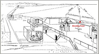
The directing point (DP) was a term used in the United States Army Coast Artillery Corps to identify a precisely surveyed point that was used as the point of reference for preparing the firing data used to aim the guns of a given Coast Artillery battery.

References

  1. 1 2 Hines, Frank T.; Ward, Franklin W. (1910). The Service of Coast Artillery. New York: Goodenough & Woglom Co. p.  305.
  2. 1 2 3 Clements, Bill (2016). The Fatal Fortress: The Guns and Fortifications of Singapore 1819 - 1953. Pen and Sword. p. 185. ISBN   978-1-4738-2961-9.
  3. 1 2 3 Maurice-Jones, Colonel K. W. (2012). The History of Coast Artillery in the British Army. Andrews UK Limited. p. 173. ISBN   978-1-78149-115-7.
  4. 1885 DRF Handbook
  5. 1892 DRF Handbook
  6. 1 2 3 Coast defence range finding at victorianforts.co.uk
  7. 1 2 3 4 Watkin depression position finders at victorianforts.co.uk
  8. 1 2 3 4 Major Watkin's Position Finder at victorianforts.co.uk
  9. 1 2 3 4 5 6 Berhow, Mark A., ed. (2015). American Seacoast Defenses, A Reference Guide (Third ed.). McLean, Virginia: CDSG Press. pp. 263–281. ISBN   978-0-9748167-3-9.
  10. Fort Gilkicker: Ranging the guns
  11. FM 4-15, Seacoast Artillery fire control and position finding. Washington: War Department. 1940. pp. 46–58.
  12. Berhow 2015, pp. 269–270.
  13. Sambrook, Stephen C (2015). The Optical Munitions Industry in Great Britain, 1888–1923. Taylor & Francis. p. 27. ISBN   978-1-317-32103-3.
  14. Berhow 2015 , pp. 291–297
  15. Hines & Ward 1910, p. 311.
  16. FM 4-15 1940 , pp. 58–71
  17. Webber, Bert (1975). Retaliation: Japanese Attacks and Allied Countermeasures on the Pacific Coast in World War II. Corvallis, Oregon: Oregon State University Press. p. 61. ISBN   0-87071-076-1.