Related Research Articles
A communications system or communication system is a collection of individual telecommunications networks systems, relay stations, tributary stations, and terminal equipment usually capable of interconnection and interoperation to form an integrated whole. The components of a communications system serve a common purpose, are technically compatible, use common procedures, respond to controls, and operate in union.

Electromagnetic compatibility (EMC) is the ability of electrical equipment and systems to function acceptably in their electromagnetic environment, by limiting the unintentional generation, propagation and reception of electromagnetic energy which may cause unwanted effects such as electromagnetic interference (EMI) or even physical damage to operational equipment. The goal of EMC is the correct operation of different equipment in a common electromagnetic environment. It is also the name given to the associated branch of electrical engineering.

In electrical engineering, ground or earth may be a reference point in an electrical circuit from which voltages are measured, a common return path for electric current, or a direct physical connection to the Earth.

A time-domain reflectometer (TDR) is an electronic instrument used to determine the characteristics of electrical lines by observing reflected pulses.

In radio engineering, an antenna or aerial is the interface between radio waves propagating through space and electric currents moving in metal conductors, used with a transmitter or receiver. In transmission, a radio transmitter supplies an electric current to the antenna's terminals, and the antenna radiates the energy from the current as electromagnetic waves. In reception, an antenna intercepts some of the power of a radio wave in order to produce an electric current at its terminals, that is applied to a receiver to be amplified. Antennas are essential components of all radio equipment.
This is an index of articles relating to electronics and electricity or natural electricity and things that run on electricity and things that use or conduct electricity.

In electronics, electrical termination is the practice of ending a transmission line with a device that matches the characteristic impedance of the line. Termination prevents signals from reflecting off the end of the transmission line. Reflections at the ends of unterminated transmission lines cause distortion, which can produce ambiguous digital signal levels and misoperation of digital systems. Reflections in analog signal systems cause such effects as video ghosting, or power loss in radio transmitter transmission lines.
In electrical engineering, partial discharge (PD) is a localized dielectric breakdown (DB) of a small portion of a solid or fluid electrical insulation (EI) system under high voltage (HV) stress. While a corona discharge (CD) is usually revealed by a relatively steady glow or brush discharge (BD) in air, partial discharges within solid insulation system are not visible.
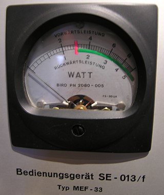
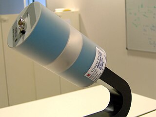
The wattmeter is an instrument for measuring the electric active power in watts of any given circuit. Electromagnetic wattmeters are used for measurement of utility frequency and audio frequency power; other types are required for radio frequency measurements.

Dielectric spectroscopy measures the dielectric properties of a medium as a function of frequency. It is based on the interaction of an external field with the electric dipole moment of the sample, often expressed by permittivity.
This is an alphabetical list of articles pertaining specifically to electrical and electronics engineering. For a thematic list, please see List of electrical engineering topics. For a broad overview of engineering, see List of engineering topics. For biographies, see List of engineers.
In electronics, crosstalk is any phenomenon by which a signal transmitted on one circuit or channel of a transmission system creates an undesired effect in another circuit or channel. Crosstalk is usually caused by undesired capacitive, inductive, or conductive coupling from one circuit or channel to another.

A network analyzer is an instrument that measures the network parameters of electrical networks. Today, network analyzers commonly measure s–parameters because reflection and transmission of electrical networks are easy to measure at high frequencies, but there are other network parameter sets such as y-parameters, z-parameters, and h-parameters. Network analyzers are often used to characterize two-port networks such as amplifiers and filters, but they can be used on networks with an arbitrary number of ports.

A test probe is a physical device used to connect electronic test equipment to a device under test (DUT). Test probes range from very simple, robust devices to complex probes that are sophisticated, expensive, and fragile. Specific types include test prods, oscilloscope probes and current probes. A test probe is often supplied as a test lead, which includes the probe, cable and terminating connector.
In electronics, an electronic switch is a switch controlled by an active electronic component or device. Without using moving parts, they are called solid state switches, which distinguishes them from mechanical switches.
EMF measurements are measurements of ambient (surrounding) electromagnetic fields that are performed using particular sensors or probes, such as EMF meters. These probes can be generally considered as antennas although with different characteristics. In fact, probes should not perturb the electromagnetic field and must prevent coupling and reflection as much as possible in order to obtain precise results. There are two main types of EMF measurements:

Electronic engineering is a sub-discipline of electrical engineering which emerged in the early 20th century and is distinguished by the additional use of active components such as semiconductor devices to amplify and control electric current flow. Previously electrical engineering only used passive devices such as mechanical switches, resistors, inductors, and capacitors.
Scanning electrochemical microscopy (SECM) is a technique within the broader class of scanning probe microscopy (SPM) that is used to measure the local electrochemical behavior of liquid/solid, liquid/gas and liquid/liquid interfaces. Initial characterization of the technique was credited to University of Texas electrochemist, Allen J. Bard, in 1989. Since then, the theoretical underpinnings have matured to allow widespread use of the technique in chemistry, biology and materials science. Spatially resolved electrochemical signals can be acquired by measuring the current at an ultramicroelectrode (UME) tip as a function of precise tip position over a substrate region of interest. Interpretation of the SECM signal is based on the concept of diffusion-limited current. Two-dimensional raster scan information can be compiled to generate images of surface reactivity and chemical kinetics.
This glossary of electrical and electronics engineering is a list of definitions of terms and concepts related specifically to electrical engineering and electronics engineering. For terms related to engineering in general, see Glossary of engineering.

An electrochemical aptamer-based (E-AB) biosensor has the ability to generate an electrochemical signal in response to specific target binding in vivo The signal is measured by a change in Faradaic current passed through an electrode. E-AB sensors are advantageous over previously reported aptamer-based sensors, such as fluorescence generating aptamers, due to their ability to detect target binding in vivo with real-time measurements. An E-AB sensor is composed of a three-electrode cell: an interrogating electrode, a reference electrode, and a counter electrode. A signal is generated within the electrochemical cell then measured and analyzed by a potentiostat. There are several biochemical and electrochemical parameters to optimize signal gain for E-AB biosensors. The density packing of DNA or RNA aptamers, the ACV frequency administered by the potentiostat, and the chemistry of the SAM are all factors that determine signal gain as well as the signal to noise ratio of target binding. E-AB biosensors provide a promising mechanism for in-situ sensing and feedback-controlled drug administration.
References
(German language, titles translated to English)
- H. Galster: pH-Messung (pH Measurement), 1990, VCH Verlagsgesellschaft mbH, ISBN 3-527-27836-2
- C.H. Hamann, W. Vielstich: Elektrochemie I (Electrochemistry I), 1975, Verlag Chemie, ISBN 3-527-21039-3
- Schröter / Lautenschläger / Bibrack: Taschenbuch der Chemie (Pocketbook of Chemistry), 2001, Verlag Harri Deutsch, ISBN 3-8171-1472-9
- U. Tietze, Ch. Schenk: Halbleiter-Schaltungstechnik (Semiconductor Circuit Technology), 2010, Springer Verlag, ISBN 978-3-642-01621-9