
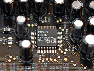
In electronics, an analog-to-digital converter is a system that converts an analog signal, such as a sound picked up by a microphone or light entering a digital camera, into a digital signal. An ADC may also provide an isolated measurement such as an electronic device that converts an analog input voltage or current to a digital number representing the magnitude of the voltage or current. Typically the digital output is a two's complement binary number that is proportional to the input, but there are other possibilities.

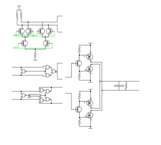
A phase-locked loop or phase lock loop (PLL) is a control system that generates an output signal whose phase is related to the phase of an input signal. There are several different types; the simplest is an electronic circuit consisting of a variable frequency oscillator and a phase detector in a feedback loop. The oscillator's frequency and phase are controlled proportionally by an applied voltage, hence the term voltage-controlled oscillator (VCO). The oscillator generates a periodic signal of a specific frequency, and the phase detector compares the phase of that signal with the phase of the input periodic signal, to adjust the oscillator to keep the phases matched.
A signal generator is one of a class of electronic devices that generates electrical signals with set properties of amplitude, frequency, and wave shape. These generated signals are used as a stimulus for electronic measurements, typically used in designing, testing, troubleshooting, and repairing electronic or electroacoustic devices, though it often has artistic uses as well.

Pulse-width modulation (PWM), also known as pulse-duration modulation (PDM) or pulse-length modulation (PLM), is a method of controlling the average power or amplitude delivered by an electrical signal. The average value of voltage fed to the load is controlled by switching the supply between 0 and 100% at a rate faster than it takes the load to change significantly. The longer the switch is on, the higher the total power supplied to the load. Along with maximum power point tracking (MPPT), it is one of the primary methods of controlling the output of solar panels to that which can be utilized by a battery. PWM is particularly suited for running inertial loads such as motors, which are not as easily affected by this discrete switching. The goal of PWM is to control a load; however, the PWM switching frequency must be selected carefully in order to smoothly do so.
In electronics, a digital-to-analog converter is a system that converts a digital signal into an analog signal. An analog-to-digital converter (ADC) performs the reverse function.

In signal processing, sampling is the reduction of a continuous-time signal to a discrete-time signal. A common example is the conversion of a sound wave to a sequence of "samples". A sample is a value of the signal at a point in time and/or space; this definition differs from the term's usage in statistics, which refers to a set of such values.

The MOS Technology 6581/8580 SID is the built-in programmable sound generator chip of the Commodore CBM-II, Commodore 64, Commodore 128, and MAX Machine home computers.
A numerically controlled oscillator (NCO) is a digital signal generator which creates a synchronous, discrete-time, discrete-valued representation of a waveform, usually sinusoidal. NCOs are often used in conjunction with a digital-to-analog converter (DAC) at the output to create a direct digital synthesizer (DDS).
A digitally controlled oscillator or DCO is used in synthesizers, microcontrollers, and software-defined radios. The name is analogous with "voltage-controlled oscillator". DCOs were designed to overcome the tuning stability limitations of early VCO designs.
This is an index of articles relating to electronics and electricity or natural electricity and things that run on electricity and things that use or conduct electricity.
A phase detector or phase comparator is a frequency mixer, analog multiplier or logic circuit that generates a signal which represents the difference in phase between two signal inputs.
A variable frequency oscillator (VFO) in electronics is an oscillator whose frequency can be tuned over some range. It is a necessary component in any tunable radio transmitter and in receivers that works by the superheterodyne principle. The oscillator controls the frequency to which the apparatus is tuned.

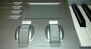
A voltage-controlled oscillator (VCO) is an electronic oscillator whose oscillation frequency is controlled by a voltage input. The applied input voltage determines the instantaneous oscillation frequency. Consequently, a VCO can be used for frequency modulation (FM) or phase modulation (PM) by applying a modulating signal to the control input. A VCO is also an integral part of a phase-locked loop. VCOs are used in synthesizers to generate a waveform whose pitch can be adjusted by a voltage determined by a musical keyboard or other input.
In a mixed-signal system, a reconstruction filter, sometimes called an anti-imaging filter, is used to construct a smooth analog signal from a digital input, as in the case of a digital to analog converter (DAC) or other sampled data output device.
A 1-bit DAC is used as a consumer electronics marketing term describing an oversampling digital-to-analog converter (DAC) that utilizes a digital noise shaping delta-sigma modulator operating at many multiples of the sampling frequency that outputs to an actual 1-bit DAC. The combination can have high signal-to-noise and hence an equivalent effective number of bits as a DAC with a larger number of bits.
A frequency synthesizer is an electronic circuit that generates a range of frequencies from a single reference frequency. Frequency synthesizers are used in many modern devices such as radio receivers, televisions, mobile telephones, radiotelephones, walkie-talkies, CB radios, cable television converter boxes, satellite receivers, and GPS systems. A frequency synthesizer may use the techniques of frequency multiplication, frequency division, direct digital synthesis, frequency mixing, and phase-locked loops to generate its frequencies. The stability and accuracy of the frequency synthesizer's output are related to the stability and accuracy of its reference frequency input. Consequently, synthesizers use stable and accurate reference frequencies, such as those provided by a crystal oscillator.
A PLL multibit or multibit PLL is a phase-locked loop (PLL) which achieves improved performance compared to a unibit PLL by using more bits. Unibit PLLs use only the most significant bit (MSB) of each counter's output bus to measure the phase, while multibit PLLs use more bits. PLLs are an essential component in telecommunications.

The CZ series is a family of low-cost phase distortion synthesizers produced by Casio in the mid-1980s. Eight models of CZ synthesizers were released: the CZ-101, CZ-230S, CZ-1000, CZ-2000S, CZ-2600S, CZ-3000, CZ-5000, and the CZ-1. Additionally, the home-keyboard model CT-6500 used 48 phase distortion presets from the CZ line. The CZ synthesizers' price at the time of their introduction made programmable synthesizers affordable enough to be purchased by garage bands. Yamaha soon introduced their own low-cost digital synthesizers, including the DX-21 (1985) and Yamaha DX100, in light of the CZ series' success.
The following outline is provided as an overview of and topical guide to electronics:
The Korg Z1 is a physical modelling sound synthesiser released in 1997. Touted as a polyphonic Prophecy, the Z1 implements 13 synthesis types, all derived from the original OASYS synthesizer.


