This article needs additional citations for verification .(December 2018) |
The original depth recorded while drilling an oil or gas well is known as the driller's depth.
This article needs additional citations for verification .(December 2018) |
The original depth recorded while drilling an oil or gas well is known as the driller's depth.
Since there is not a single reference or measurement system for calculating the depth in sub-surface environments, two engineers talking about a single drilling might give different answers when asked to give a measurement of depth.
The two main depth references used in the "downhole" (i.e. sub-surface) environment are driller's depths and logger's depths (also called wireline logger's depths). These measurement systems are recorded quite differently and logger's depths are generally considered the more accurate of the two:
There are several parts of the drilling site to be considered while measuring:
In practice, driller's depth measurement is a manual operation, not changed significantly over the years and there are many facets of the system with potential to introduce errors and inconsistencies. This process was first described by Reistle and Sikes in 1938, [1] and has not changed significantly.
The bulk of the drill string is drill pipe which has a nominal length of 9.6 meter per pipe section, however, in reality, not all pipes are the same length. Weakened or damaged ends of a pipe section will be reworked, resulting in reduced length.
Steel pipe has a "male" connection at one end (called the pin) and a "female" connection at the other end (called the box) and as each section of pipe is lowered into the hole it is connected to the pipe preceding it by threading together the male and female components. Drill pipe connections (or drill pipe/collar, or collar/bit and any other connection) must have a very good sealing surface because high pressure mud will be traveling through the pipe and any pitted or galled areas could be quickly eroded out. This is usually referred to as a wash-out, or words to that effect, and can occur in any part of the drill string or bottom hole assembly. Because of this pipe is routinely inspected before and after use. Any imperfections are eliminated one of two actions:
Different methods of measuring the drill pipe length also have a significant effect on the accuracy of the measurement made. Pipe "strapping" is commonly used to define drill pipe length, where the pipe is measured on the pipe racks using a (steel) measure tape. These results are noted in a tally book, and the drillstring length is hence defined. However, the accuracy of this measurement method is limited by the application of the steel tape correctly, the reading accuracy, and a host of environmental issues. A significant improvement to drill pipe measurement accuracy is provided using laser, and accuracies can be easily improved by around factor 4. It is also important to note the calibration conditions so that corrections can be applied based on these calibration conditions. This is specifically true for temperature when defining the thermal elongation. [2]
Tracking and recording of drill pipe at the rig site starts when individual joints are picked up. Joint numbers are manually marked on the side of the pipe. Typically three sections of pipe are joined into a stand (of about 27–29 m in length) and stacked in rows of 10, with their base resting on the drill floor. Prior to running in the hole each stand is manually measured with a steel tape measure and the measurement recorded in a computer spreadsheet (previously a pipe tally book was used) alongside the stand number. To confirm at any stage what depth the drill bit is operating at, the driller consults the pipe tally records, and measures the length of the current stand of drill pipe below the rig floor.
Another potential area for error is the bottom hole assembly. This consists of the drill bit, drill collars and stabilizers. It can also include a downhole motor, tools for measurement while drilling and logging while drilling. Errors come about if the total bottom hole assembly is not correctly measured or recorded. Bottom hole assembly changes may be made during operations and if these changes are not recorded then the depths will be incorrect.
Ideally the bottom hole assembly is operated to minimize "sagging" within the borehole. Pipe stretch and compression will occur from time to time but are not corrected for during normal operations, even though they can introduce fairly significant cumulative errors on driller's depth, particularly in deep wells or in areas of hard rock.
If exploration derived prognosticated depths are significantly different from the driller's depths, for example by 10−30 m, then warning bells come up – it is possible a pipe section or stand has been left off the calculations. If this is suspected, then the drill string should be measured (in tension) when the string is next pulled out of the hole, and the results checked with the tally. Mudloggers should be vigilant, as they provide the opportunity to cross check with the drilling company.
An important aspect in this is identifying the required accuracy for the logged driller's depths. If drillers and geologists are "OK" with (for example, +/- 15 m) at these depths, but later the reservoir engineers trying to map fluid water contacts require a higher level of precision (for example, +/- 3 m), then by the time the drilling is finished the higher level of accuracy cannot be recreated. This leads to the concept of true along-hole depth, where the measurements made are defined using the accuracy of the pipe length calibration method and (if any) the accuracy of the corrections applied the correction methodology.
One methodology that has been introduced is called Driller Way-point Depth (patent applied) [3] which results in true along-hole depth. The measurement uncertainty is then a combination of the drill pipe length measurement accuracy, how accurately the correction parameters are measured, and the fidelity of the correction model applied.
For some deep wells, e.g. 7,000 m or 25,000 ft deep, the drill pipe elongation due to its own weight and temperature must be taken into account. This can be on the order of 24 m (80 ft). Wireline does not behave this way: it tends to lengthen under tension but shorten with increasing temperature. One can only assume by how much this net effect varies. Wireline depth correction for temperature and tension has been around since before the days of computer data acquisition, and is generally seen as reliable. Based on experience, the impact on a geological model previously based on wireline depth, when drilling at greater than 7,000 m and using logging while drilling (driller's) depths, can introduce differences in marker depths of up to 25 m (80 ft): the driller's depths are consistently higher than the more reliable wireline depths.
The driller's survey do not call this elongation an uncertainty but rather call it bias or error. For the example above, in addition to the 25 m (+80 ft) bias, there would be about ± 3 m/12 ft to 10 m/30 ft residual uncertainty depending on hole inclination. There are a few in the industry who know how to correct for this real time and some service companies have developed conceptual or prototype tools/processes to account for this elongation effect. In future, these corrections should become standard practice for the industry, but they are not As of 2013 [update] . The determination of an accurate depth has not traditionally been a popular area of research primarily because of lack of recognition of the impact that depth measurement inaccuracy has on the value of the depth data. The impact of errors in depth is most critical when integrating data from more than one well, e.g. to build a reservoir model. This impact, however, is usually apparent only long after the depth measurement process has occurred and is not seen as being an issue during the well construction.
Recognition of the value of depth measurement accuracy at the planning stages of drilling, and then during the drilling process itself, is a precursor to achieving improving accuracy. [4]
In petroleum exploration and development, formation evaluation is used to determine the ability of a borehole to produce petroleum. Essentially, it is the process of "recognizing a commercial well when you drill one".

A borehole is a narrow shaft bored in the ground, either vertically or horizontally. A borehole may be constructed for many different purposes, including the extraction of water, other liquids, or gases. It may also be part of a geotechnical investigation, environmental site assessment, mineral exploration, temperature measurement, as a pilot hole for installing piers or underground utilities, for geothermal installations, or for underground storage of unwanted substances, e.g. in carbon capture and storage.

In the oil and gas industry, the term wireline usually refers to the use of multi-conductor, single conductor or slickline cable, or "wireline", as a conveyance for the acquisition of subsurface petrophysical and geophysical data and the delivery of well construction services such as pipe recovery, perforating, plug setting and well cleaning and fishing. The subsurface geophysical and petrophysical information results in the description and analysis of subsurface geology, reservoir properties and production characteristics.

Directional drilling is the practice of drilling non-vertical bores. It can be broken down into four main groups: oilfield directional drilling, utility installation directional drilling, directional boring, and surface in seam (SIS), which horizontally intersects a vertical bore target to extract coal bed methane.
Well logging, also known as borehole logging is the practice of making a detailed record of the geologic formations penetrated by a borehole. The log may be based either on visual inspection of samples brought to the surface or on physical measurements made by instruments lowered into the hole. Some types of geophysical well logs can be done during any phase of a well's history: drilling, completing, producing, or abandoning. Well logging is performed in boreholes drilled for the oil and gas, groundwater, mineral and geothermal exploration, as well as part of environmental and geotechnical studies.
Well control is the technique used in oil and gas operations such as drilling, well workover and well completion for maintaining the hydrostatic pressure and formation pressure to prevent the influx of formation fluids into the wellbore. This technique involves the estimation of formation fluid pressures, the strength of the subsurface formations and the use of casing and mud density to offset those pressures in a predictable fashion. Understanding pressure and pressure relationships is important in well control.
Logging while drilling (LWD) is a technique of conveying well logging tools into the well borehole downhole as part of the bottom hole assembly (BHA).
A drilling rig is used to create a borehole or well in the earth's sub-surface, for example in order to extract natural resources such as gas or oil. During such drilling, data is acquired from the drilling rig sensors for a range of purposes such as: decision-support to monitor and manage the smooth operation of drilling; to make detailed records of the geologic formations penetrated by a borehole; to generate operations statistics and performance benchmarks such that improvements can be identified, and to provide well planners with accurate historical operations-performance data with which to perform statistical risk analysis for future well operations. The terms measurement while drilling (MWD), and logging while drilling (LWD) are not used consistently throughout the industry. Although these terms are related, within the context of this section, the term measurement while drilling refers to directional-drilling measurements, e.g. for decision support for the wellbore path, while LWD refers to measurements concerning the geological formations penetrated while drilling.
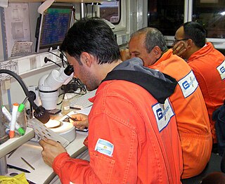
Mud logging is the creation of a detailed record of a borehole by examining the cuttings of rock brought to the surface by the circulating drilling medium. Mud logging is usually performed by a third-party mud logging company. This provides well owners and producers with information about the lithology and fluid content of the borehole while drilling. Historically it is the earliest type of well log. Under some circumstances compressed air is employed as a circulating fluid, rather than mud. Although most commonly used in petroleum exploration, mud logging is also sometimes used when drilling water wells and in other mineral exploration, where drilling fluid is the circulating medium used to lift cuttings out of the hole. In hydrocarbon exploration, hydrocarbon surface gas detectors record the level of natural gas brought up in the mud. A mobile laboratory is situated by the mud logging company near the drilling rig or on deck of an offshore drilling rig, or on a drill ship.
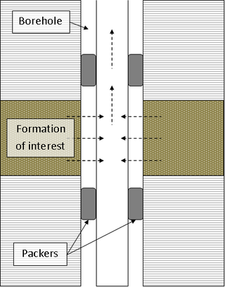
A drill stem test (DST) is a procedure for isolating and testing the pressure, permeability and productive capacity of a geological formation during the drilling of a well. The test is an important measurement of pressure behaviour at the drill stem and is a valuable way of obtaining information on the formation fluid and establishing whether a well has found a commercial hydrocarbon reservoir.

In the oil and gas industry, coiled tubing refers to a long metal pipe, normally 1 to 3.25 in in diameter which is supplied spooled on a large reel. It is used for interventions in oil and gas wells and sometimes as production tubing in depleted gas wells. Coiled tubing is often used to carry out operations similar to wirelining. The main benefits over wireline are the ability to pump chemicals through the coil and the ability to push it into the hole rather than relying on gravity. Pumping can be fairly self-contained, almost a closed system, since the tube is continuous instead of jointed pipe. For offshore operations, the 'footprint' for a coiled tubing operation is generally larger than a wireline spread, which can limit the number of installations where coiled tubing can be performed and make the operation more costly. A coiled tubing operation is normally performed through the drilling derrick on the oil platform, which is used to support the surface equipment, although on platforms with no drilling facilities a self-supporting tower can be used instead. For coiled tubing operations on sub-sea wells a mobile offshore drilling unit (MODU) e.g. semi-submersible, drillship etc. has to be utilized to support all the surface equipment and personnel, whereas wireline can be carried out from a smaller and cheaper intervention vessel. Onshore, they can be run using smaller service rigs, and for light operations a mobile self-contained coiled tubing rig can be used.
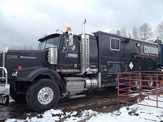
Slickline refers to a single strand wire which is used to run a variety of tools down into the wellbore for several purposes. It is used during well drilling operations in the oil and gas industry. In general, it can also describe a niche of the industry that involves using a slickline truck or doing a slickline job. Slickline looks like a long, smooth, unbraided wire, often shiny, silver/chrome in appearance. It comes in varying lengths, according to the depth of wells in the area it is used up to 35,000 feet in length. It is used to lower and raise downhole tools used in oil and gas well maintenance to the appropriate depth of the drilled well.
In the oil and gas industry, depth in a well is the distance along a well between a point of interest and a reference point or surface. It is the most common method of reference for locations in the well, and therefore, in oil industry speech, "depth" also refers to the location itself.
Oilfield terminology refers to the jargon used by those working in fields within and related to the upstream segment of the petroleum industry. It includes words and phrases describing professions, equipment, and procedures specific to the industry. It may also include slang terms used by oilfield workers to describe the same.

Tripping pipe is the physical act of pulling the drill string out of the wellbore and then running it back in. This is done by physically breaking out or disconnecting every other 2 or 3 joints of drill pipe at a time and racking them vertically in the derrick. When feasible the driller will start each successive trip on a different "break" so that after several trips fresh pipe dope will have been applied to every segment of the drill string.
IntelliServ is a National Oilwell Varco brand that manufactures and sells a broadband networked drilling string system used to transmit downhole information to the surface in a drilling operation.
Pipe recovery is a specific wireline operation used in the oil and gas industry, when the drill string becomes stuck downhole. Stuck pipe prevents the drill rig from continuing operations. This results in costly downtime, ranging anywhere from $10,000-1,000,000 per day of downtime, therefore it is critical to resolve the problem as quickly as possible. Pipe recovery is the process by which the location of the stuck pipe is identified, and the free pipe is separated from the stuck pipe either by a backoff or a chemical cut. This allows fishing tools to subsequently be run down hole to latch onto and remove the stuck pipe.

Ice drilling allows scientists studying glaciers and ice sheets to gain access to what is beneath the ice, to take measurements along the interior of the ice, and to retrieve samples. Instruments can be placed in the drilled holes to record temperature, pressure, speed, direction of movement, and for other scientific research, such as neutrino detection.
Wireline quality assurance and quality control is a set of requirements and operating procedures which take place before, during, and after the wireline logging job. The main merits of wireline QA/QC include accuracy and precision of recorded data and information. Accuracy is a measure of the correctness of the result and is generally depended on how well the systematic errors are controlled and compensated for. Precision is depended on how well random errors are analysed and overcame.