In electronics, the figures of merit of an amplifier are numerical measures that characterize its properties and performance. Figures of merit can be given as a list of specifications that include properties such as gain, bandwidth, noise and linearity, among others listed in this article. Figures of merit are important for determining the suitability of a particular amplifier for an intended use.

An amplifier, electronic amplifier or (informally) amp is an electronic device that can increase the power of a signal. It is a two-port electronic circuit that uses electric power from a power supply to increase the amplitude of a signal applied to its input terminals, producing a proportionally greater amplitude signal at its output. The amount of amplification provided by an amplifier is measured by its gain: the ratio of output voltage, current, or power to input. An amplifier is a circuit that has a power gain greater than one.
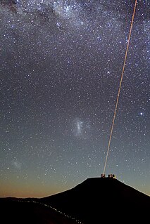
An optical amplifier is a device that amplifies an optical signal directly, without the need to first convert it to an electrical signal. An optical amplifier may be thought of as a laser without an optical cavity, or one in which feedback from the cavity is suppressed. Optical amplifiers are important in optical communication and laser physics. They are used as optical repeaters in the long distance fiberoptic cables which carry much of the world's telecommunication links.
Noise figure (NF) and noise factor (F) are measures of degradation of the signal-to-noise ratio (SNR), caused by components in a signal chain. It is a number by which the performance of an amplifier or a radio receiver can be specified, with lower values indicating better performance.
In electronics, noise temperature is one way of expressing the level of available noise power introduced by a component or source. The power spectral density of the noise is expressed in terms of the temperature that would produce that level of Johnson–Nyquist noise, thus:
A low-noise amplifier (LNA) is an electronic amplifier that amplifies a very low-power signal without significantly degrading its signal-to-noise ratio. An amplifier will increase the power of both the signal and the noise present at its input, but the amplifier will also introduce some additional noise. LNAs are designed to minimize that additional noise. Designers can minimize additional noise by choosing low-noise components, operating points, and circuit topologies. Minimizing additional noise must balance with other design goals such as power gain and impedance matching.

A spectrum analyzer measures the magnitude of an input signal versus frequency within the full frequency range of the instrument. The primary use is to measure the power of the spectrum of known and unknown signals. The input signal that most common spectrum analyzers measure is electrical; however, spectral compositions of other signals, such as acoustic pressure waves and optical light waves, can be considered through the use of an appropriate transducer. Spectrum analyzers for other types of signals also exist, such as optical spectrum analyzers which use direct optical techniques such as a monochromator to make measurements.

A low-dropout regulator is a DC linear voltage regulator that can regulate the output voltage even when the supply voltage is very close to the output voltage.
Radio receiver design includes the electronic design of different components of a radio receiver which processes the radio frequency signal from an antenna in order to produce usable information such as audio. The complexity of a modern receiver and the possible range of circuitry and methods employed are more generally covered in electronics and communications engineering. The term radio receiver is understood in this article to mean any device which is intended to receive a radio signal in order to generate useful information from the signal, most notably a recreation of the so-called baseband signal which modulated the radio signal at the time of transmission in a communications or broadcast system.

In electronics, noise is an unwanted disturbance in an electrical signal. Noise generated by electronic devices varies greatly as it is produced by several different effects.
In telecommunication, a measuring receiver or measurement receiver is a calibrated laboratory-grade radio receiver designed to measure the characteristics of radio signals. The parameters of such receivers can usually be adjusted over a much wider range of values than is the case with other radio receivers. Their circuitry is optimized for stability and to enable calibration and reproducible results. Some measurement receivers also have especially robust input circuits that can survive brief impulses of more than 1000 V, as they can occur during measurements of radio signals on power lines and other conductors.
A total harmonic distortion analyzer calculates the total harmonic content of a sinewave with some distortion, expressed as total harmonic distortion (THD). A typical application is to determine the THD of an amplifier by using a very-low-distortion sinewave input and examining the output. The figure measured will include noise, and any contribution from imperfect filtering out of the fundamental frequency. Harmonic-by-harmonic measurement, without wideband noise, can be measured by a more complex wave analyser.
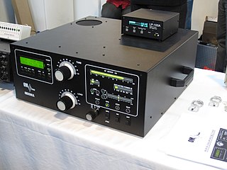
A valve RF amplifier or tube amplifier (U.S.) is a device for electrically amplifying the power of an electrical radio frequency signal.
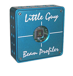
A laser beam profiler captures, displays, and records the spatial intensity profile of a laser beam at a particular plane transverse to the beam propagation path. Since there are many types of lasers — ultraviolet, visible, infrared, continuous wave, pulsed, high-power, low-power — there is an assortment of instrumentation for measuring laser beam profiles. No single laser beam profiler can handle every power level, pulse duration, repetition rate, wavelength, and beam size.
A minimum detectable signal is a signal at the input of a system whose power allows it to be detected over the background electronic noise of the detector system. It can alternately be defined as a signal that produces a signal-to-noise ratio of a given value m at the output. In practice, m is usually chosen to be greater than unity. In some literature, the name sensitivity is used for this concept.
A noise-figure meter is an instrument for measuring the noise figure of an amplifier, mixer, or similar device. An example instrument is the 1983-era Agilent 8970A. 8970A Noise Figure Meter is a Keysight product numbers that were formerly part of Agilent.

A noise generator is a circuit that produces electrical noise. Noise generators are used to test signals for measuring noise figure, frequency response, and other parameters. Noise generators are also used for generating random numbers.
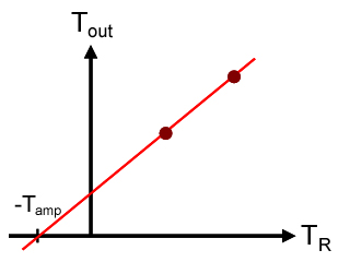
The Y-factor method is a widely used technique for measuring the gain and noise temperature of an amplifier. It is based on the Johnson–Nyquist noise of a resistor at two different, known temperatures.
An RF chain is a cascade of electronic components and sub-units which may include amplifiers, filters, mixers, attenuators and detectors. It can take many forms, for example, as a wide-band receiver-detector for electronic warfare (EW) applications, as a tunable narrow-band receiver for communications purposes, as a repeater in signal distribution systems, or as an amplifier and up-converters for a transmitter-driver. In this article, the term RF covers the frequency range "Medium Frequencies" up to "Microwave Frequencies", i.e. from 100 kHz to 20 GHz.

Two-tone testing is a means of testing electronic components and systems, particularly radio systems, for intermodulation distortion. It consists of simultaneously injecting two sinusoidal signals of different frequencies (tones) into the component or system. Intermodulation distortion usually occurs in active components like amplifiers, but can also occur in some circumstances in passive items such as cable connectors, especially at high power.
