Fanning friction factor

Last updated

The Fanning friction factor, named after John Thomas Fanning, is a dimensionless number used as a local parameter in continuum mechanics calculations. It is defined as the ratio between the local shear stress and the local flow kinetic energy density:

Contents

[1] [2]

where:

where the dynamic pressure is given by:

where:

In particular the shear stress at the wall can, in turn, be related to the pressure loss by multiplying the wall shear stress by the wall area ( for a pipe with circular cross section) and dividing by the cross-sectional flow area ( for a pipe with circular cross section). Thus

Fanning friction factor formula

Fanning friction factor for tube flow Fanning friction factor.JPG
Fanning friction factor for tube flow

This friction factor is one-fourth of the Darcy friction factor, so attention must be paid to note which one of these is meant in the "friction factor" chart or equation consulted. Of the two, the Fanning friction factor is the more commonly used by chemical engineers and those following the British convention.

The formulas below may be used to obtain the Fanning friction factor for common applications.

The Darcy friction factor can also be expressed as [3]

where:

For laminar flow in a round tube

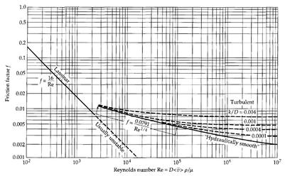
From the chart, it is evident that the friction factor is never zero, even for smooth pipes because of some roughness at the microscopic level.

The friction factor for laminar flow of Newtonian fluids in round tubes is often taken to be: [4]

[5] [2]

where Re is the Reynolds number of the flow.

For a square channel the value used is:

For turbulent flow in a round tube

Hydraulically smooth piping

Blasius developed an expression of friction factor in 1913 for the flow in the regime .

[6] [2]

Koo introduced another explicit formula in 1933 for a turbulent flow in region of

[7] [8]

Pipes/tubes of general roughness

When the pipes have certain roughness , this factor must be taken in account when the Fanning friction factor is calculated. The relationship between pipe roughness and Fanning friction factor was developed by Haaland (1983) under flow conditions of

[2] [9] [8]

where

  • is the roughness of the inner surface of the pipe (dimension of length)
  • D is inner pipe diameter;

The Swamee–Jain equation is used to solve directly for the Darcy–Weisbach friction factor f for a full-flowing circular pipe. It is an approximation of the implicit Colebrook–White equation. [10]

Fully rough conduits

As the roughness extends into turbulent core, the Fanning friction factor becomes independent of fluid viscosity at large Reynolds numbers, as illustrated by Nikuradse and Reichert (1943) for the flow in region of . The equation below has been modified from the original format which was developed for Darcy friction factor by a factor of

[11] [12]

General expression

For the turbulent flow regime, the relationship between the Fanning friction factor and the Reynolds number is more complex and is governed by the Colebrook equation [6] which is implicit in :

Various explicit approximations of the related Darcy friction factor have been developed for turbulent flow.

Stuart W. Churchill [5] developed a formula that covers the friction factor for both laminar and turbulent flow. This was originally produced to describe the Moody chart, which plots the Darcy-Weisbach Friction factor against Reynolds number. The Darcy Weisbach Formula , also called Moody friction factor, is 4 times the Fanning friction factor and so a factor of has been applied to produce the formula given below.

  • Re, Reynolds number (unitless);
  • ε, roughness of the inner surface of the pipe (dimension of length);
  • D, inner pipe diameter;
  • ln is the Natural logarithm;
  • Here, is not the Darcy-Weisbach Friction factor , is 4 times lower than ;

Flows in non-circular conduits

Due to geometry of non-circular conduits, the Fanning friction factor can be estimated from algebraic expressions above by using hydraulic radius when calculating for Reynolds number

Application

The friction head can be related to the pressure loss due to friction by dividing the pressure loss by the product of the acceleration due to gravity and the density of the fluid. Accordingly, the relationship between the friction head and the Fanning friction factor is:

where:

Related Research Articles

In thermal fluid dynamics, the Nusselt number is the ratio of total heat transfer to conductive heat transfer at a boundary in a fluid. Total heat transfer combines conduction and convection. Convection includes both advection and diffusion (conduction). The conductive component is measured under the same conditions as the convective but for a hypothetically motionless fluid. It is a dimensionless number, closely related to the fluid's Rayleigh number.

In fluid dynamics, turbulence or turbulent flow is fluid motion characterized by chaotic changes in pressure and flow velocity. It is in contrast to a laminar flow, which occurs when a fluid flows in parallel layers, with no disruption between those layers.

In fluid dynamics, the Darcy–Weisbach equation is an empirical equation that relates the head loss, or pressure loss, due to friction along a given length of pipe to the average velocity of the fluid flow for an incompressible fluid. The equation is named after Henry Darcy and Julius Weisbach. Currently, there is no formula more accurate or universally applicable than the Darcy-Weisbach supplemented by the Moody diagram or Colebrook equation.

<span class="mw-page-title-main">Boundary layer</span> Layer of fluid in the immediate vicinity of a bounding surface

In physics and fluid mechanics, a boundary layer is the thin layer of fluid in the immediate vicinity of a bounding surface formed by the fluid flowing along the surface. The fluid's interaction with the wall induces a no-slip boundary condition. The flow velocity then monotonically increases above the surface until it returns to the bulk flow velocity. The thin layer consisting of fluid whose velocity has not yet returned to the bulk flow velocity is called the velocity boundary layer.

<span class="mw-page-title-main">Bingham plastic</span> Material which is solid at low stress but becomes viscous at high stress

In materials science, a Bingham plastic is a viscoplastic material that behaves as a rigid body at low stresses but flows as a viscous fluid at high stress. It is named after Eugene C. Bingham who proposed its mathematical form.

Darcy's law is an equation that describes the flow of a fluid through a porous medium. The law was formulated by Henry Darcy based on results of experiments on the flow of water through beds of sand, forming the basis of hydrogeology, a branch of earth sciences. It is analogous to Ohm's law in electrostatics, linearly relating the volume flow rate of the fluid to the hydraulic head difference via the hydraulic conductivity. In fact, the Darcy's law is a special case of the Stokes equation for the momentum flux, in turn deriving from the momentum Navier-Stokes equation.

In thermodynamics, the heat transfer coefficient or film coefficient, or film effectiveness, is the proportionality constant between the heat flux and the thermodynamic driving force for the flow of heat. It is used in calculating the heat transfer, typically by convection or phase transition between a fluid and a solid. The heat transfer coefficient has SI units in watts per square meter per kelvin (W/m2K).

<span class="mw-page-title-main">Plug flow</span> Simple model of fluid flow in a pipe

In fluid mechanics, plug flow is a simple model of the velocity profile of a fluid flowing in a pipe. In plug flow, the velocity of the fluid is assumed to be constant across any cross-section of the pipe perpendicular to the axis of the pipe. The plug flow model assumes there is no boundary layer adjacent to the inner wall of the pipe.

The Manning formula or Manning's equation is an empirical formula estimating the average velocity of a liquid in an open channel flow. However, this equation is also used for calculation of flow variables in case of flow in partially full conduits, as they also possess a free surface like that of open channel flow. All flow in so-called open channels is driven by gravity.

The Hazen–Williams equation is an empirical relationship which relates the flow of water in a pipe with the physical properties of the pipe and the pressure drop caused by friction. It is used in the design of water pipe systems such as fire sprinkler systems, water supply networks, and irrigation systems. It is named after Allen Hazen and Gardner Stewart Williams.

The Ergun equation, derived by the Turkish chemical engineer Sabri Ergun in 1952, expresses the friction factor in a packed column as a function of the modified Reynolds number.

In fluid dynamics, turbulence kinetic energy (TKE) is the mean kinetic energy per unit mass associated with eddies in turbulent flow. Physically, the turbulence kinetic energy is characterized by measured root-mean-square (RMS) velocity fluctuations. In the Reynolds-averaged Navier Stokes equations, the turbulence kinetic energy can be calculated based on the closure method, i.e. a turbulence model.

<span class="mw-page-title-main">Friction loss</span> Loss of fluid or energy or money through friction

The term friction loss has a number of different meanings, depending on its context.

Taylor dispersion or Taylor diffusion is an apparent or effective diffusion of some scalar field arising on the large scale due to the presence of a strong, confined, zero-mean shear flow on the small scale. Essentially, the shear acts to smear out the concentration distribution in the direction of the flow, enhancing the rate at which it spreads in that direction. The effect is named after the British fluid dynamicist G. I. Taylor, who described the shear-induced dispersion for large Peclet numbers. The analysis was later generalized by Rutherford Aris for arbitrary values of the Peclet number. The dispersion process is sometimes also referred to as the Taylor-Aris dispersion.

In fluid dynamics, the Darcy friction factor formulae are equations that allow the calculation of the Darcy friction factor, a dimensionless quantity used in the Darcy–Weisbach equation, for the description of friction losses in pipe flow as well as open-channel flow.

<span class="mw-page-title-main">Moody chart</span> Graph used in fluid dynamics

In engineering, the Moody chart or Moody diagram is a graph in non-dimensional form that relates the Darcy–Weisbach friction factor fD, Reynolds number Re, and surface roughness for fully developed flow in a circular pipe. It can be used to predict pressure drop or flow rate down such a pipe.

In nonideal fluid dynamics, the Hagen–Poiseuille equation, also known as the Hagen–Poiseuille law, Poiseuille law or Poiseuille equation, is a physical law that gives the pressure drop in an incompressible and Newtonian fluid in laminar flow flowing through a long cylindrical pipe of constant cross section. It can be successfully applied to air flow in lung alveoli, or the flow through a drinking straw or through a hypodermic needle. It was experimentally derived independently by Jean Léonard Marie Poiseuille in 1838 and Gotthilf Heinrich Ludwig Hagen, and published by Hagen in 1839 and then by Poiseuille in 1840–41 and 1846. The theoretical justification of the Poiseuille law was given by George Stokes in 1845.

The Chézy Formula is a semi-empirical resistance equation which estimates mean flow velocity in open channel conduits. The relationship was conceptualized and developed in 1768 by French physicist and engineer Antoine de Chézy (1718–1798) while designing Paris's water canal system. Chézy discovered a similarity parameter that could be used for estimating flow characteristics in one channel based on the measurements of another. The Chézy formula is a pioneering formula in the field of fluid mechanics which relates the flow of water through an open channel with the channel's dimensions and slope. It was expanded and modified by Irish Engineer Robert Manning in 1889. Manning's modifications to the Chézy formula allowed the entire similarity parameter to be calculated by channel characteristics rather than by experimental measurements. Today, the Chézy and Manning equations continue to accurately estimate open channel fluid flow and are standard formulas in various fields related to fluid mechanics and hydraulics, including physics, mechanical engineering and civil engineering.

Shear velocity, also called friction velocity, is a form by which a shear stress may be re-written in units of velocity. It is useful as a method in fluid mechanics to compare true velocities, such as the velocity of a flow in a stream, to a velocity that relates shear between layers of flow.

<span class="mw-page-title-main">Reynolds number</span> Ratio of inertial to viscous forces acting on a liquid

In fluid dynamics, the Reynolds number is a dimensionless quantity that helps predict fluid flow patterns in different situations by measuring the ratio between inertial and viscous forces. [fluid dynamics citation needed] At low Reynolds numbers, flows tend to be dominated by laminar (sheet-like) flow, while at high Reynolds numbers, flows tend to be turbulent. The turbulence results from differences in the fluid's speed and direction, which may sometimes intersect or even move counter to the overall direction of the flow. These eddy currents begin to churn the flow, using up energy in the process, which for liquids increases the chances of cavitation.

References

  1. Khan, Kaleem (2015). Fluid Mechanics and Machinery. Oxford University Press India. ISBN   9780199456772. OCLC   961849291.
  2. 1 2 3 4 Lightfoot, Edwin N.; Stewart, Warren E. (2007). Transport phenomena. Wiley. ISBN   9780470115398. OCLC   288965242.
  3. Cengel, Yunus; Ghajar, Afshin (2014). Heat and Mass Transfer: Fundamentals and Applications. McGraw-Hill. ISBN   978-0-07-339818-1.
  4. McCabe, Warren; Smith, Julian; Harriott, Peter (2004). Unit Operations of Chemical Engineering (7th ed.). New York, NY: McGraw-Hill. pp. 98–119. ISBN   978-0072848236.
  5. 1 2 Churchill, S.W. (1977). "Friction factor equation spans all fluid-flow regimes". Chemical Engineering. 84 (24): 91–92.
  6. 1 2 Colebrook, C. F.; White, C. M. (3 August 1937). "Experiments with Fluid Friction in Roughened Pipes". Proceedings of the Royal Society of London. Series A, Mathematical and Physical Sciences. 161 (906): 367–381. Bibcode:1937RSPSA.161..367C. doi:10.1098/rspa.1937.0150. JSTOR   96790.
  7. Klinzing, E. G. (2010). Pneumatic conveying of solids : a theoretical and practical approach. Springer. ISBN   9789048136094. OCLC   667991206.
  8. 1 2 Bragg, R (1995). Fluid Flow for Chemical and Process Engineers. Butterworth-Heinemann [Imprint]. ISBN   9780340610589. OCLC   697596706.
  9. Heldman, Dennis R. (2009). Introduction to food engineering. Academic. ISBN   9780123709004. OCLC   796034676.
  10. Swamee, P.K.; Jain, A.K. (1976). "Explicit equations for pipe-flow problems". Journal of the Hydraulics Division. 102 (5): 657–664. doi:10.1061/JYCEAJ.0004542.
  11. Rehm, Bill (2012). Underbalanced drilling limits and extremes. Gulf Publishing Company. ISBN   9781933762050. OCLC   842343889.
  12. Pavlou, Dimitrios G. (2013). Composite materials in piping applications : design, analysis and optimization of subsea and onshore pipelines from FRP materials. DEStech Publications. ISBN   9781605950297. OCLC   942612658.

Further reading