Friction Losses
Before being able to use the minor head losses in an equation, the losses in the system due to friction must also be calculated.
Equation for friction losses:
 [5] [3] [1]
 = Frictional head loss
 = Downstream velocity
 = Gravity of Earth
 = Hydraulic radius
 =Total length of piping
 = Fanning friction factor
Total Head Loss
After both minor losses and friction losses have been calculated, these values can be summed to find the total head loss.
Equation for total head loss,  , can be simplified and rewritten as:
 [5]
[5]
= Frictional head loss
= Downstream velocity
= Gravity of Earth
= Hydraulic radius
=Total length of piping
= Fanning friction factor
 = Sum of all kinetic energy factors in system
Once calculated, the total head loss can be used to solve the Bernoulli Equation and find unknown values of the system. [1] [5]

In celestial mechanics, escape velocity or escape speed is the minimum speed needed for a free, non-propelled object to escape from the gravitational influence of a primary body, thus reaching an infinite distance from it. It is typically stated as an ideal speed, ignoring atmospheric friction. Although the term "escape velocity" is common, it is more accurately described as a speed than a velocity because it is independent of direction; the escape speed increases with the mass of the primary body and decreases with the distance from the primary body. The escape speed thus depends on how far the object has already traveled, and its calculation at a given distance takes into account that without new acceleration it will slow down as it travels—due to the massive body's gravity—but it will never quite slow to a stop.
In fluid dynamics, the Darcy–Weisbach equation is an empirical equation that relates the head loss, or pressure loss, due to friction along a given length of pipe to the average velocity of the fluid flow for an incompressible fluid. The equation is named after Henry Darcy and Julius Weisbach. Currently, there is no formula more accurate or universally applicable than the Darcy-Weisbach supplemented by the Moody diagram or Colebrook equation.

A Bingham plastic is a viscoplastic material that behaves as a rigid body at low stresses but flows as a viscous fluid at high stress. It is named after Eugene C. Bingham who proposed its mathematical form.

Soil mechanics is a branch of soil physics and applied mechanics that describes the behavior of soils. It differs from fluid mechanics and solid mechanics in the sense that soils consist of a heterogeneous mixture of fluids and particles but soil may also contain organic solids and other matter. Along with rock mechanics, soil mechanics provides the theoretical basis for analysis in geotechnical engineering, a subdiscipline of civil engineering, and engineering geology, a subdiscipline of geology. Soil mechanics is used to analyze the deformations of and flow of fluids within natural and man-made structures that are supported on or made of soil, or structures that are buried in soils. Example applications are building and bridge foundations, retaining walls, dams, and buried pipeline systems. Principles of soil mechanics are also used in related disciplines such as geophysical engineering, coastal engineering, agricultural engineering, hydrology and soil physics.

Hydraulic head or piezometric head is a specific measurement of liquid pressure above a vertical datum.
The Manning formula is an empirical formula estimating the average velocity of a liquid flowing in a conduit that does not completely enclose the liquid, i.e., open channel flow. However, this equation is also used for calculation of flow variables in case of flow in partially full conduits, as they also possess a free surface like that of open channel flow. All flow in so-called open channels is driven by gravity. It was first presented by the French engineer Philippe Gauckler in 1867, and later re-developed by the Irish engineer Robert Manning in 1890.

In fluid mechanics and hydraulics, open-channel flow is a type of liquid flow within a conduit with a free surface, known as a channel. The other type of flow within a conduit is pipe flow. These two types of flow are similar in many ways but differ in one important respect: open-channel flow has a free surface, whereas pipe flow does not.
The Fanning friction factor, named after John Thomas Fanning, is a dimensionless number used as a local parameter in continuum mechanics calculations. It is defined as the ratio between the local shear stress and the local flow kinetic energy density:
The Hazen–Williams equation is an empirical relationship which relates the flow of water in a pipe with the physical properties of the pipe and the pressure drop caused by friction. It is used in the design of water pipe systems such as fire sprinkler systems, water supply networks, and irrigation systems. It is named after Allen Hazen and Gardner Stewart Williams.

The term friction loss has a number of different meanings, depending on its context.
In fluid dynamics, pipe network analysis is the analysis of the fluid flow through a hydraulics network, containing several or many interconnected branches. The aim is to determine the flow rates and pressure drops in the individual sections of the network. This is a common problem in hydraulic design.

The shallow-water equations are a set of hyperbolic partial differential equations that describe the flow below a pressure surface in a fluid. The shallow-water equations in unidirectional form are also called Saint-Venant equations, after Adhémar Jean Claude Barré de Saint-Venant.
In fluid dynamics, the Darcy friction factor formulae are equations that allow the calculation of the Darcy friction factor, a dimensionless quantity used in the Darcy–Weisbach equation, for the description of friction losses in pipe flow as well as open-channel flow.
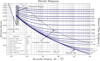
In engineering, the Moody chart or Moody diagram is a graph in non-dimensional form that relates the Darcy–Weisbach friction factor fD, Reynolds number Re, and surface roughness for fully developed flow in a circular pipe. It can be used to predict pressure drop or flow rate down such a pipe.
In nonideal fluid dynamics, the Hagen–Poiseuille equation, also known as the Hagen–Poiseuille law, Poiseuille law or Poiseuille equation, is a physical law that gives the pressure drop in an incompressible and Newtonian fluid in laminar flow flowing through a long cylindrical pipe of constant cross section. It can be successfully applied to air flow in lung alveoli, or the flow through a drinking straw or through a hypodermic needle. It was experimentally derived independently by Jean Léonard Marie Poiseuille in 1838 and Gotthilf Heinrich Ludwig Hagen, and published by Poiseuille in 1840–41 and 1846. The theoretical justification of the Poiseuille law was given by George Stokes in 1845.
The Chézy formula is an semi-empirical resistance equation which estimates mean flow velocity in open channel conduits. The relationship was realized and developed in 1768 by French physicist and engineer Antoine de Chézy (1718-1798) while designing Paris's water canal system. Chézy discovered a similarity parameter that could be used for estimating flow characteristics in one channel based on the measurements of another. The Chézy formula relates the flow of water through an open channel with the channel's dimensions and slope. The Chézy equation is a pioneering formula in the field of Fluid Mechanics, and was expanded and modified by Irish Engineer Robert Manning in 1889. Manning's modifications to the Chézy formula allowed the entire similarity parameter to be calculated by channel characteristics rather than by experimental measurements. Today, the Chézy and Manning equations continue to accurately estimate open channel fluid flow and are standard formulas in all fields that relate to fluid mechanics and hydraulics, including physics, mechanical engineering and civil engineering.

The Reynolds number helps predict flow patterns in different fluid flow situations. At low Reynolds numbers, flows tend to be dominated by laminar (sheet-like) flow, while at high Reynolds numbers flows tend to be turbulent. The turbulence results from differences in the fluid's speed and direction, which may sometimes intersect or even move counter to the overall direction of the flow. These eddy currents begin to churn the flow, using up energy in the process, which for liquids increases the chances of cavitation. Reynolds numbers are an important dimensionless quantity in fluid mechanics.
Hydraulic compressors are a type of compressor that is designed to convert hydraulic power to pneumatic power. It is used across various industries to improve the efficiency of certain types of machinery. Hydraulic compressors have a hydraulic pump to push air through a pipe, which forces a motor to spin. The motor powers the internal air compressor, releasing air in a chamber as a result. Compressors became more popularized in 1799 when Englishman George Medhurst invented a motorized air compressor as a means for propulsion. They have technologically advanced to the point where they can achieve greater force and precision than humans.
The theory of sonics is a branch of continuum mechanics which describes the transmission of mechanical energy through vibrations. The birth of the theory of sonics is the publication of the book A treatise on transmission of power by vibrations in 1918 by the Romanian scientist Gogu Constantinescu.
ONE of the fundamental problems of mechanical engineering is that of transmitting energy found in nature, after suitable transformation, to some point at which can be made available for performing useful work. The methods of transmitting power known and practised by engineers are broadly included in two classes: mechanical including hydraulic, pneumatic and wire rope methods; and electrical methods....According to the new system, energy is transmitted from one point to another, which may be at a considerable distance, by means of impressed variations of pressure or tension producing longitudinal vibrations in solid, liquid or gaseous columns. The energy is transmitted by periodic changes of pressure and volume in the longitudinal direction and may be described as wave transmission of power, or mechanical wave transmission. – Gogu Constantinescu
The standard step method (STM) is a computational technique utilized to estimate one-dimensional surface water profiles in open channels with gradually varied flow under steady state conditions. It uses a combination of the energy, momentum, and continuity equations to determine water depth with a given a friction slope , channel slope , channel geometry, and also a given flow rate. In practice, this technique is widely used through the computer program HEC-RAS, developed by the US Army Corps of Engineers Hydrologic Engineering Center (HEC).