A rectifier is an electrical device that converts alternating current (AC), which periodically reverses direction, to direct current (DC), which flows in only one direction. The reverse operation is performed by an inverter.

A power supply is an electrical device that supplies electric power to an electrical load. The main purpose of a power supply is to convert electric current from a source to the correct voltage, current, and frequency to power the load. As a result, power supplies are sometimes referred to as electric power converters. Some power supplies are separate standalone pieces of equipment, while others are built into the load appliances that they power. Examples of the latter include power supplies found in desktop computers and consumer electronics devices. Other functions that power supplies may perform include limiting the current drawn by the load to safe levels, shutting off the current in the event of an electrical fault, power conditioning to prevent electronic noise or voltage surges on the input from reaching the load, power-factor correction, and storing energy so it can continue to power the load in the event of a temporary interruption in the source power.

A power inverter, inverter, or invertor is a power electronic device or circuitry that changes direct current (DC) to alternating current (AC). The resulting AC frequency obtained depends on the particular device employed. Inverters do the opposite of rectifiers which were originally large electromechanical devices converting AC to DC.
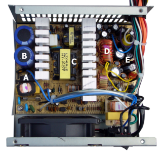
A switched-mode power supply (SMPS), also called switching-mode power supply, switch-mode power supply, switched power supply, or simply switcher, is an electronic power supply that incorporates a switching regulator to convert electrical power efficiently.
In all fields of electrical engineering, power conversion is the process of converting electric energy from one form to another. A power converter is an electrical or electro-mechanical device for converting electrical energy. A power converter can convert alternating current (AC) into direct current (DC) and vice versa; change the voltage or frequency of the current or do some combination of these. The power converter can be as simple as a transformer or it can be a far more complex system, such as a resonant converter. The term can also refer to a class of electrical machinery that is used to convert one frequency of alternating current into another. Power conversion systems often incorporate redundancy and voltage regulation.
A DC-to-DC converter is an electronic circuit or electromechanical device that converts a source of direct current (DC) from one voltage level to another. It is a type of electric power converter. Power levels range from very low to very high.

A voltage regulator is a system designed to automatically maintain a constant voltage. It may use a simple feed-forward design or may include negative feedback. It may use an electromechanical mechanism, or electronic components. Depending on the design, it may be used to regulate one or more AC or DC voltages.

A flyback transformer (FBT), also called a line output transformer (LOPT), is a special type of electrical transformer. It was initially designed to generate high-voltage sawtooth signals at a relatively high frequency. In modern applications, it is used extensively in switched-mode power supplies for both low (3 V) and high voltage supplies.
Inrush current, input surge current, or switch-on surge is the maximal instantaneous input current drawn by an electrical device when first turned on. Alternating-current electric motors and transformers may draw several times their normal full-load current when first energized, for a few cycles of the input waveform. Power converters also often have inrush currents much higher than their steady-state currents, due to the charging current of the input capacitance. The selection of over-current-protection devices such as fuses and circuit breakers is made more complicated when high inrush currents must be tolerated. The over-current protection must react quickly to overload or short-circuit faults but must not interrupt the circuit when the inrush current flows.

A blocking oscillator is a simple configuration of discrete electronic components which can produce a free-running signal, requiring only a resistor, a transformer, and one amplifying element such as a transistor or vacuum tube. The name is derived from the fact that the amplifying element is cut-off or "blocked" for most of the duty cycle, producing periodic pulses on the principle of a relaxation oscillator. The non-sinusoidal output is not suitable for use as a radio-frequency local oscillator, but it can serve as a timing generator, to power lights, LEDs, EL wire, or small neon indicators. If the output is used as an audio signal, the simple tones are also sufficient for applications such as alarms or a Morse code practice device. Some cameras use a blocking oscillator to strobe the flash prior to a shot to reduce the red-eye effect.
In electronics, a bleeder resistor, bleeder load, leakage resistor, capacitor discharge resistor or safety discharge resistor is a resistor connected in parallel with the output of a high-voltage power supply circuit for the purpose of discharging the electric charge stored in the power supply's filter capacitors when the equipment is turned off, for safety reasons. It eliminates the possibility of a leftover charge causing electric shock if people handle or service the equipment in the off state, believing it is safe. A bleeder resistor is usually a standard resistor rather than a specialized component.

A boost converter or step-up converter is a DC-to-DC converter that increases voltage, while decreasing current, from its input (supply) to its output (load).
An H-bridge is an electronic circuit that switches the polarity of a voltage applied to a load. These circuits are often used in robotics and other applications to allow DC motors to run forwards or backwards. The name is derived from its common schematic diagram representation, with four switching elements configured as the branches of a letter "H" and the load connected as the cross-bar.

The single-ended primary-inductor converter (SEPIC) is a type of DC/DC converter that allows the electrical potential (voltage) at its output to be greater than, less than, or equal to that at its input. The output of the SEPIC is controlled by the duty cycle of the control switch (S1).

A variety of types of electrical transformer are made for different purposes. Despite their design differences, the various types employ the same basic principle as discovered in 1831 by Michael Faraday, and share several key functional parts.

A flyback diode is any diode connected across an inductor used to eliminate flyback, which is the sudden voltage spike seen across an inductive load when its supply current is suddenly reduced or interrupted. It is used in circuits in which inductive loads are controlled by switches, and in switching power supplies and inverters.
A Royer oscillator is an electronic relaxation oscillator that employs a saturable-core transformer in the main power path. It was invented and patented in April 1954 by Richard L. Bright & George H. Royer, who are listed as co-inventors on the patent. It has the advantages of simplicity, low component count, rectangle waveforms, and transformer isolation. As well as being an inverter, it can be used as a galvanically-isolated DC-DC converter when the transformer output winding is connected to a suitable rectifying stage, in which case the resulting apparatus is usually called a "Royer Converter".

A joule thief is a minimalist self-oscillating voltage booster that is small, low-cost, and easy to build, typically used for driving small loads, such as driving an LED using a 1.5 volt battery. This circuit is also known by other names such as blocking oscillator, joule ringer, or vampire torch. It can use nearly all of the energy in a single-cell electric battery, even far below the voltage where other circuits consider the battery fully discharged ; hence the name, which suggests the notion that the circuit is stealing energy or "joules" from the source – the term is a pun on "jewel thief". The circuit is a variant of the blocking oscillator that forms an unregulated voltage boost converter.
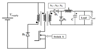
The forward converter is a DC/DC converter that uses a transformer to increase or decrease the output voltage and provide galvanic isolation for the load. With multiple output windings, it is possible to provide both higher and lower voltage outputs simultaneously.
This glossary of power electronics is a list of definitions of terms and concepts related to power electronics in general and power electronic capacitors in particular. For more definitions in electric engineering, see Glossary of electrical and electronics engineering. For terms related to engineering in general, see Glossary of engineering.