
An analog computer or analogue computer is a type of computer that uses the continuous variation aspect of physical phenomena such as electrical, mechanical, or hydraulic quantities to model the problem being solved. In contrast, digital computers represent varying quantities symbolically and by discrete values of both time and amplitude.
Digital subscriber line is a family of technologies that are used to transmit digital data over telephone lines. In telecommunications marketing, the term DSL is widely understood to mean asymmetric digital subscriber line (ADSL), the most commonly installed DSL technology, for Internet access.

In telecommunication, a four-wire circuit is a two-way circuit using two paths so arranged that the respective signals are transmitted in one direction only by one path and in the other direction by the other path. The four-wire circuit gets its name from the fact that is uses four conductors to create two complete electrical circuits, one for each direction. The two separate circuits (channels) allow full-duplex operation with low crosstalk.

A hybrid transformer is a type of directional coupler which is designed to be configured as a circuit having four ports that are conjugate in pairs, implemented using one or more transformers. It is a particular case of the more general concept of a hybrid coupler.

Network topology is the arrangement of the elements of a communication network. Network topology can be used to define or describe the arrangement of various types of telecommunication networks, including command and control radio networks, industrial fieldbusses and computer networks.

A printed circuit board (PCB), also called printed wiring board (PWB), is a medium used to connect or "wire" components to one another in a circuit. It takes the form of a laminated sandwich structure of conductive and insulating layers: each of the conductive layers is designed with a pattern of traces, planes and other features etched from one or more sheet layers of copper laminated onto and/or between sheet layers of a non-conductive substrate. Electrical components may be fixed to conductive pads on the outer layers in the shape designed to accept the component's terminals, generally by means of soldering, to both electrically connect and mechanically fasten them to it. Another manufacturing process adds vias, plated-through holes that allow interconnections between layers.

Components of an electrical circuit are electrically connected if an electric current can run between them through an electrical conductor. An electrical connector is an electromechanical device used to create an electrical connection between parts of an electrical circuit, or between different electrical circuits, thereby joining them into a larger circuit. Most electrical connectors have a gender – i.e. the male component, called a plug, connects to the female component, or socket. The connection may be removable, require a tool for assembly and removal, or serve as a permanent electrical joint between two points. An adapter can be used to join dissimilar connectors.

A registered jack (RJ) is a standardized telecommunication network interface for connecting voice and data equipment to a service provided by a local exchange carrier or long distance carrier. Registered interfaces were first defined in the Universal Service Ordering Code (USOC) system of the Bell System in the United States for complying with the registration program for customer-supplied telephone equipment mandated by the Federal Communications Commission (FCC) in the 1970s. They were subsequently codified in title 47 of the Code of Federal Regulations Part 68. Registered jack connections began to see use after their invention in 1973 by Bell Labs. The specification includes physical construction, wiring, and signal semantics. Accordingly, registered jacks are primarily named by the letters RJ, followed by two digits that express the type. Additional letter suffixes indicate minor variations. For example, RJ11, RJ14, and RJ25 are the most commonly used interfaces for telephone connections for one-, two-, and three-line service, respectively. Although these standards are legal definitions in the United States, some interfaces are used worldwide.
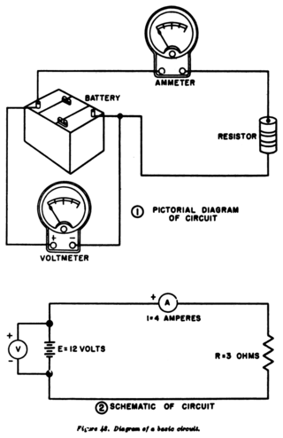
A circuit diagram is a graphical representation of an electrical circuit. A pictorial circuit diagram uses simple images of components, while a schematic diagram shows the components and interconnections of the circuit using standardized symbolic representations. The presentation of the interconnections between circuit components in the schematic diagram does not necessarily correspond to the physical arrangements in the finished device.

A telephone jack and a telephone plug are electrical connectors for connecting a telephone set or other telecommunications apparatus to the telephone wiring inside a building, establishing a connection to a telephone network. The plug is inserted into its counterpart, the jack, which is commonly affixed to a wall or baseboard. The standards for telephone jacks and plugs vary from country to country, though the 6P2C style modular plug has become by far the most common type.

A telephone line or telephone circuit is a single-user circuit on a telephone communication system. It is designed to reproduce speech of a quality that is understandable. It is the physical wire or other signaling medium connecting the user's telephone apparatus to the telecommunications network, and usually also implies a single telephone number for billing purposes reserved for that user. Telephone lines are used to deliver landline telephone service and digital subscriber line (DSL) phone cable service to the premises. Telephone overhead lines are connected to the public switched telephone network. The voltage at a subscriber's network interface is typically 48 V between the ring and tip wires, with tip near ground and ring at –48 V.

In analog telephony, a telephone hybrid is the component at the ends of a subscriber line of the public switched telephone network (PSTN) that converts between two-wire and four-wire forms of bidirectional audio paths. When used in broadcast facilities to enable the airing of telephone callers, the broadcast-quality telephone hybrid is known as a broadcast telephone hybrid or telephone balance unit.

A business telephone system is a telephone system typically used in business environments, encompassing the range of technology from the key telephone system (KTS) to the private branch exchange (PBX).
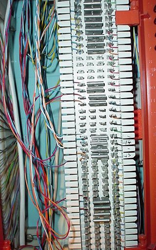
A 66 block is a type of punch-down block used to connect sets of wires in a telephone system. They have been manufactured in four common configurations, A, B, E and M. A and B styles have the clip rows on 0.25" centers while E and M have the clip rows on 0.20" centers. The A blocks have 25 slotted holes on the left side for position the incoming building cable with a 50 slot fanning strip on the right side for distribution cables. They have been obsolete for many years. The B & M styles have 50 slot fanning strip on both sides. The B style is used mainly in distribution panels where several destinations need to connect to the same source. The M blocks are often used to connect a single instrument to such a distribution block. The E style has 5 columns of 10 2 clips rows and are used for transitioning from the 25 pair distribution cable to a 25 pair RJ21 style female ribbon connector.
In telecommunication, a two-wire circuit is characterized by supporting transmission in two directions simultaneously, as opposed to four-wire circuits, which have separate pairs for transmit and receive. The subscriber local loop from the telco central office are almost all two wire for analog baseband voice calls, and converted to four-wire at the line card back when telephone switching was performed on baseband audio. Today the audio is digitized and processed completely in the digital domain upstream from the local loop.
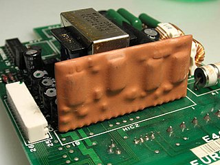
A hybrid integrated circuit (HIC), hybrid microcircuit, hybrid circuit or simply hybrid is a miniaturized electronic circuit constructed of individual devices, such as semiconductor devices and passive components, bonded to a substrate or printed circuit board (PCB). A PCB having components on a Printed Wiring Board (PWB) is not considered a true hybrid circuit according to the definition of MIL-PRF-38534.

BORSCHT is an acronym for the set of functions performed by a subscriber line interface circuit (SLIC) in the line card of a telecommunication system providing plain old telephone service. The letters represent the following functions: battery feed (B), overvoltage protection (O), ringing (R), signaling (S), coding (C), hybrid (H), and test (T).
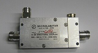
Power dividers and directional couplers are passive devices used mostly in the field of radio technology. They couple a defined amount of the electromagnetic power in a transmission line to a port enabling the signal to be used in another circuit. An essential feature of directional couplers is that they only couple power flowing in one direction. Power entering the output port is coupled to the isolated port but not to the coupled port. A directional coupler designed to split power equally between two ports is called a hybrid coupler.
In building wiring, multiway switching is the interconnection of two or more electrical switches to control an electrical load from more than one location. A common application is in lighting, where it allows the control of lamps from multiple locations, for example in a hallway, stairwell, or large room.
In theoretical computer science, the circuit satisfiability problem is the decision problem of determining whether a given Boolean circuit has an assignment of its inputs that makes the output true. In other words, it asks whether the inputs to a given Boolean circuit can be consistently set to 1 or 0 such that the circuit outputs 1. If that is the case, the circuit is called satisfiable. Otherwise, the circuit is called unsatisfiable. In the figure to the right, the left circuit can be satisfied by setting both inputs to be 1, but the right circuit is unsatisfiable.