A galvanostat (also known as amperostat) is a control and measuring device capable of keeping the current through an electrolytic cell in coulometric titrations constant, disregarding changes in the load itself.
Its main feature is its nearly "infinite" (i.e. extremely high in respect to common loads) internal resistance.
The designation "galvanostat" is mainly used in electrochemistry: this device differs from common constant current sources by its ability to supply and measure a wide range of currents (from picoamperes to amperes) of both polarities.
The galvanostat responds to changes in the resistance of the cell by varying its output potential: as Ohm's law shows,

the variable system resistance and the controlled voltage are directly proportional, i.e.

where
 is the electric current that is kept constant
 is the output control voltage of the amperostat
 is the electrical resistance that varies;
thus, an increase of the load resistance implies an increase of the voltage the amperostat applies to the load.

A negative-feedback amplifier is an electronic amplifier that subtracts a fraction of its output from its input, so that negative feedback opposes the original signal. The applied negative feedback can improve its performance and reduces sensitivity to parameter variations due to manufacturing or environment. Because of these advantages, many amplifiers and control systems use negative feedback.

In electronics, negative resistance (NR) is a property of some electrical circuits and devices in which an increase in voltage across the device's terminals results in a decrease in electric current through it.

In electronics, a common-base amplifier is one of three basic single-stage bipolar junction transistor (BJT) amplifier topologies, typically used as a current buffer or voltage amplifier.

A differential amplifier is a type of electronic amplifier that amplifies the difference between two input voltages but suppresses any voltage common to the two inputs. It is an analog circuit with two inputs and and one output , in which the output is ideally proportional to the difference between the two voltages:

In electronics, a voltage divider is a passive linear circuit that produces an output voltage (Vout) that is a fraction of its input voltage (Vin). Voltage division is the result of distributing the input voltage among the components of the divider. A simple example of a voltage divider is two resistors connected in series, with the input voltage applied across the resistor pair and the output voltage emerging from the connection between them.

In electronics, a common collector amplifier is one of three basic single-stage bipolar junction transistor (BJT) amplifier topologies, typically used as a voltage buffer.
A current mirror is a circuit designed to copy a current through one active device by controlling the current in another active device of a circuit, keeping the output current constant regardless of loading. The current being "copied" can be, and sometimes is, a varying signal current. Conceptually, an ideal current mirror is simply an ideal inverting current amplifier that reverses the current direction as well. Or it can consist of a current-controlled current source (CCCS). The current mirror is used to provide bias currents and active loads to circuits. It can also be used to model a more realistic current source.
Transconductance, also infrequently called mutual conductance, is the electrical characteristic relating the current through the output of a device to the voltage across the input of a device. Conductance is the reciprocal of resistance.

A current source is an electronic circuit that delivers or absorbs an electric current which is independent of the voltage across it.
A load cell converts a force such as tension, compression, pressure, or torque into an electrical signal that can be measured and standardized. It is a force transducer. As the force applied to the load cell increases, the electrical signal changes proportionally. The most common types of load cell are pneumatic, hydraulic, and strain gauges.
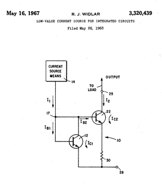
A Widlar current source is a modification of the basic two-transistor current mirror that incorporates an emitter degeneration resistor for only the output transistor, enabling the current source to generate low currents using only moderate resistor values.
The cascode is a two-stage amplifier that consists of a common-emitter stage feeding into a common-base stage.
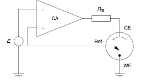
A potentiostat is the electronic hardware required to control a three electrode cell and run most electroanalytical experiments. A Bipotentiostat and polypotentiostat are potentiostats capable of controlling two working electrodes and more than two working electrodes, respectively.
This article illustrates some typical operational amplifier applications. A non-ideal operational amplifier's equivalent circuit has a finite input impedance, a non-zero output impedance, and a finite gain. A real op-amp has a number of non-ideal features as shown in the diagram, but here a simplified schematic notation is used, many details such as device selection and power supply connections are not shown. Operational amplifiers are optimised for use with negative feedback, and this article discusses only negative-feedback applications. When positive feedback is required, a comparator is usually more appropriate. See Comparator applications for further information.

In electronics, a current divider is a simple linear circuit that produces an output current (IX) that is a fraction of its input current (IT). Current division refers to the splitting of current between the branches of the divider. The currents in the various branches of such a circuit will always divide in such a way as to minimize the total energy expended.

An attenuator is an electronic device that reduces the power of a signal without appreciably distorting its waveform.
An active load or dynamic load is a component or a circuit that functions as a current-stable nonlinear resistor.
In electronics, a differentiator is a circuit that is designed such that the output of the circuit is approximately directly proportional to the rate of change of the input. A true differentiator cannot be physically realized, because it has infinite gain at infinite frequency. A similar effect can be achieved, however, by limiting the gain above some frequency. The differentiator circuit is essentially a high-pass filter.
An active differentiator includes some form of amplifier, while a passive differentiator is made only of resistors, capacitors and inductors.
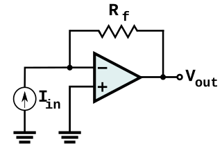
In electronics, a transimpedance amplifier (TIA) is a current to voltage converter, almost exclusively implemented with one or more operational amplifiers. The TIA can be used to amplify the current output of Geiger–Müller tubes, photo multiplier tubes, accelerometers, photo detectors and other types of sensors to a usable voltage. Current to voltage converters are used with sensors that have a current response that is more linear than the voltage response. This is the case with photodiodes where it is not uncommon for the current response to have better than 1% nonlinearity over a wide range of light input. The transimpedance amplifier presents a low impedance to the photodiode and isolates it from the output voltage of the operational amplifier. In its simplest form a transimpedance amplifier has just a large valued feedback resistor, Rf. The gain of the amplifer is set by this resistor and because the amplifier is in an inverting configuration, has a value of -Rf. There are several different configurations of transimpedance amplifiers, each suited to a particular application. The one factor they all have in common is the requirement to convert the low-level current of a sensor to a voltage. The gain, bandwidth, as well as current and voltage offsets change with different types of sensors, requiring different configurations of transimpedance amplifiers.
The operational amplifier integrator is an electronic integration circuit. Based on the operational amplifier (op-amp), it performs the mathematical operation of integration with respect to time; that is, its output voltage is proportional to the input voltage integrated over time.


