Potentiostat

Last updated
Fig. 1 : Schematic of a potentiostat. Potentiostat3.png
Fig. 1 : Schematic of a potentiostat.

A potentiostat is the electronic hardware required to control a three electrode cell and run most electroanalytical experiments. A Bipotentiostat and polypotentiostat are potentiostats capable of controlling two working electrodes and more than two working electrodes, respectively. [1] [2] [3] [4]

Contents

The system functions by maintaining the potential of the working electrode at a constant level with respect to the reference electrode by adjusting the current at an auxiliary electrode. The heart of the different potentiostatic electronic circuits is an operational amplifier (op amp). [5] It consists of an electric circuit which is usually described in terms of simple op amps.

Primary use

This equipment is fundamental to modern electrochemical studies using three electrode systems for investigations of reaction mechanisms related to redox chemistry and other chemical phenomena. The dimensions of the resulting data depend on the experiment. In voltammetry, electric current in amps is plotted against electric potential in voltage. In a bulk electrolysis total coulombs passed (total electric charge) is plotted against time in seconds even though the experiment measures electric current (amperes) over time. This is done to show that the experiment is approaching an expected number of coulombs.

Most early potentiostats could function independently, providing data output through a physical data trace. Modern potentiostats are designed to interface with a personal computer and operate through a dedicated software package. The automated software allows the user rapidly to shift between experiments and experimental conditions. The computer allows data to be stored and analyzed more effectively, rapidly, and accurately than the earlier standalone devices.

Basic relationships

A potentiostat is a control and measuring device. It comprises an electric circuit which controls the potential across the cell by sensing changes in its resistance, varying accordingly the current supplied to the system: a higher resistance will result in a decreased current, while a lower resistance will result in an increased current, in order to keep the voltage constant as described by Ohm's law.

As a result, the variable system resistance and the controlled current are inversely proportional

  • is the output electric current of the potentiostat
  • is the voltage that is kept constant
  • is the electrical resistance that varies.

Principles of operation

Since 1942, when the English electrochemist Archie Hickling (University of Leicester) built the first three electrode potentiostat, [6] substantial progress has been made to improve the instrument. Hickling's device used a third electrode, the reference electrode to control the cell potential automatically. Up until the present day his principle has remained in use. At a glance, a potentiostat measures the potential difference between the working and the reference electrode, applies the current through the counter electrode and measures the current as an voltage drop over a series resistor ( in Fig. 1).

The control amplifier (CA) is responsible for maintaining the voltage between the reference and the working electrode as closely as possible to the voltage of the input source . It adjusts its output to automatically control the cell current so that a condition of equilibrium is satisfied. The theory of operation is best understood using the equations below.

Prior to observing the following equations, one may note that, from an electrical point of view, the electrochemical cell and the current measurement resistor may be regarded as two impedances (Fig. 2). includes in series with the interfacial impedance of the counter electrode and the solution resistance between the counter and the reference. represents the interfacial impedance of the working electrode in series with the solution resistance between the working and the reference electrodes.

Fig. 2 : Schematic of a potentiostat, with electrochemical cell replaced by two impedances. Potentiostat4.png
Fig. 2 : Schematic of a potentiostat, with electrochemical cell replaced by two impedances.

The role of the control amplifier is to amplify the potential difference between the positive (or noninverting) input and the negative (or inverting) input. This may be translated mathematically into the following equation:

. (1)

where is the amplification factor of the CA. At this point the assumption may be made that a negligible amount of current is flowing through the reference electrode. This correlates to physical phenomenon since the reference electrode is connected to a high impedance electrometer. Thus, the cell current may be described in two ways:

(2)

and

. (3)

Combining Eqs. (2) and (3) yields Eq. (4):

(4)

where is the fraction of the output voltage of the control amplifier returned to its negative input; namely the feedback factor:

.

Combining Eqs. (1) and (4) yields Eq. (6):

. (6)

When the quantity becomes very large with respect to one, Eq. (6) reduces to Eq. (7), which is one of the negative feedback equations:

. (7)

Eq. (7) proves that the control amplifier works to keep the voltage between the reference and the working close to the input source voltage.

Software control

Replacing the CA, a control algorithm can maintain a constant voltage between the reference electrode and the working electrode. [7] This algorithm is based on the rule of proportion:

. (8)
  • is the last measured cell voltage between the working electrode (WE) and the counter electrode (CE).
  • is the last measured electrochemical potential, i.e. the voltage between the reference electrode and WE to be kept constant.
  • is the next cell voltage to be set, i.e. the controller output.
  • is the setpoint, i.e. the desired .

If the measurement intervals of Eq. (8) are kept constant, the control algorithm sets the cell voltage so to keep as close as possible to the setpoint . The algorithm requires software-controllable hardware such as a digital multimeter, a power supply, and a double-pole double-throw relay. The relay is necessary to switch polarity.

Significant features

In electrochemical experiments the electrodes are the pieces of equipment that comes in immediate contact with the analyte. For this reason the electrodes are very important for determining the experimental result. The electrode surface may or may not catalyze chemical reactions. The size of the electrodes affects the magnitude of the currents passed which can affect signal to noise. But electrodes are not the only limiting factor for electrochemical experiments, the potentiostat also has a limited range of operation. The following are a few significant features that vary between instruments.

See also

Related Research Articles

<span class="mw-page-title-main">Electrochemistry</span> Branch of chemistry

Electrochemistry is the branch of physical chemistry concerned with the relationship between electrical potential difference and identifiable chemical change. These reactions involve electrons moving via an electronically-conducting phase between electrodes separated by an ionically conducting and electronically insulating electrolyte.

<span class="mw-page-title-main">Electrical impedance</span> Opposition of a circuit to a current when a voltage is applied

In electrical engineering, impedance is the opposition to alternating current presented by the combined effect of resistance and reactance in a circuit.

<span class="mw-page-title-main">Electromotive force</span> Electrical action produced by a non-electrical source

In electromagnetism and electronics, electromotive force is an energy transfer to an electric circuit per unit of electric charge, measured in volts. Devices called electrical transducers provide an emf by converting other forms of energy into electrical energy. Other electrical equipment also produce an emf, such as batteries, which convert chemical energy, and generators, which convert mechanical energy. This energy conversion is achieved by physical forces applying physical work on electric charges. However, electromotive force itself is not a physical force, and ISO/IEC standards have deprecated the term in favor of source voltage or source tension instead.

<span class="mw-page-title-main">Negative resistance</span> Property that an increasing voltage results in a decreasing current

In electronics, negative resistance (NR) is a property of some electrical circuits and devices in which an increase in voltage across the device's terminals results in a decrease in electric current through it.

<span class="mw-page-title-main">Series and parallel circuits</span> Types of electrical circuits

Two-terminal components and electrical networks can be connected in series or parallel. The resulting electrical network will have two terminals, and itself can participate in a series or parallel topology. Whether a two-terminal "object" is an electrical component or an electrical network is a matter of perspective. This article will use "component" to refer to a two-terminal "object" that participates in the series/parallel networks.

<span class="mw-page-title-main">Voltage divider</span> Linear circuit that produces an output voltage that is a fraction of its input voltage

In electronics, a voltage divider (also known as a potential divider) is a passive linear circuit that produces an output voltage (Vout) that is a fraction of its input voltage (Vin). Voltage division is the result of distributing the input voltage among the components of the divider. A simple example of a voltage divider is two resistors connected in series, with the input voltage applied across the resistor pair and the output voltage emerging from the connection between them.

<span class="mw-page-title-main">Voltage clamp</span>

The voltage clamp is an experimental method used by electrophysiologists to measure the ion currents through the membranes of excitable cells, such as neurons, while holding the membrane voltage at a set level. A basic voltage clamp will iteratively measure the membrane potential, and then change the membrane potential (voltage) to a desired value by adding the necessary current. This "clamps" the cell membrane at a desired constant voltage, allowing the voltage clamp to record what currents are delivered. Because the currents applied to the cell must be equal to the current going across the cell membrane at the set voltage, the recorded currents indicate how the cell reacts to changes in membrane potential. Cell membranes of excitable cells contain many different kinds of ion channels, some of which are voltage-gated. The voltage clamp allows the membrane voltage to be manipulated independently of the ionic currents, allowing the current–voltage relationships of membrane channels to be studied.

<span class="mw-page-title-main">Output impedance</span> Measure of the opposition to current flow by an internal electrical load

In electrical engineering, the output impedance of an electrical network is the measure of the opposition to current flow (impedance), both static (resistance) and dynamic (reactance), into the load network being connected that is internal to the electrical source. The output impedance is a measure of the source's propensity to drop in voltage when the load draws current, the source network being the portion of the network that transmits and the load network being the portion of the network that consumes.

In electrical engineering and electronics, a network is a collection of interconnected components. Network analysis is the process of finding the voltages across, and the currents through, all network components. There are many techniques for calculating these values; however, for the most part, the techniques assume linear components. Except where stated, the methods described in this article are applicable only to linear network analysis.

<span class="mw-page-title-main">Internal resistance</span> Impedance of a linear circuits Thévenin representation

In electrical engineering, a practical electric power source which is a linear circuit may, according to Thévenin's theorem, be represented as an ideal voltage source in series with an impedance. This impedance is termed the internal resistance of the source. When the power source delivers current, the measured voltage output is lower than the no-load voltage; the difference is the voltage drop caused by the internal resistance. The concept of internal resistance applies to all kinds of electrical sources and is useful for analyzing many types of circuits.

<span class="mw-page-title-main">Dielectric spectroscopy</span>

Dielectric spectroscopy measures the dielectric properties of a medium as a function of frequency. It is based on the interaction of an external field with the electric dipole moment of the sample, often expressed by permittivity.

<span class="mw-page-title-main">Widlar current source</span> Electronic circuit

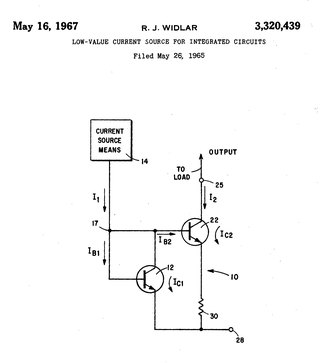
A Widlar current source is a modification of the basic two-transistor current mirror that incorporates an emitter degeneration resistor for only the output transistor, enabling the current source to generate low currents using only moderate resistor values.

<span class="mw-page-title-main">Voltammetry</span> Method of analyzing electrochemical reactions

Voltammetry is a category of electroanalytical methods used in analytical chemistry and various industrial processes. In voltammetry, information about an analyte is obtained by measuring the current as the potential is varied. The analytical data for a voltammetric experiment comes in the form of a voltammogram, which plots the current produced by the analyte versus the potential of the working electrode.

This article illustrates some typical operational amplifier applications. A non-ideal operational amplifier's equivalent circuit has a finite input impedance, a non-zero output impedance, and a finite gain. A real op-amp has a number of non-ideal features as shown in the diagram, but here a simplified schematic notation is used, many details such as device selection and power supply connections are not shown. Operational amplifiers are optimised for use with negative feedback, and this article discusses only negative-feedback applications. When positive feedback is required, a comparator is usually more appropriate. See Comparator applications for further information.

<span class="mw-page-title-main">Capacitor types</span> Manufacturing styles of an electronic device

Capacitors are manufactured in many styles, forms, dimensions, and from a large variety of materials. They all contain at least two electrical conductors, called plates, separated by an insulating layer (dielectric). Capacitors are widely used as parts of electrical circuits in many common electrical devices.

<span class="mw-page-title-main">Current divider</span> Simple linear circuit

In electronics, a current divider is a simple linear circuit that produces an output current (IX) that is a fraction of its input current (IT). Current division refers to the splitting of current between the branches of the divider. The currents in the various branches of such a circuit will always divide in such a way as to minimize the total energy expended.

In electronics, the Miller effect accounts for the increase in the equivalent input capacitance of an inverting voltage amplifier due to amplification of the effect of capacitance between the input and output terminals. The virtually increased input capacitance due to the Miller effect is given by

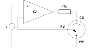
A galvanostat is a control and measuring device capable of keeping the current through an electrolytic cell in coulometric titrations constant, disregarding changes in the load itself.

In electrochemistry, the Butler–Volmer equation, also known as Erdey-Grúz–Volmer equation, is one of the most fundamental relationships in electrochemical kinetics. It describes how the electrical current through an electrode depends on the voltage difference between the electrode and the bulk electrolyte for a simple, unimolecular redox reaction, considering that both a cathodic and an anodic reaction occur on the same electrode:

<span class="mw-page-title-main">Performance and modelling of AC transmission</span>

Performance modelling is the abstraction of a real system into a simplified representation to enable the prediction of performance. The creation of a model can provide insight into how a proposed or actual system will or does work. This can, however, point towards different things to people belonging to different fields of work.

References

  1. Bard, A.J.; Faulkner, L.R. (2000). Electrochemical Methods: Fundamentals and Applications. New York: John Wiley & Sons, 2nd Edition, ISBN   0-471-40521-3.
  2. Cynthia G. Zoski (Editor) (2007). Handbook of Electrochemistry. Elsevier, ISBN   0-444-51958-0
  3. Peter T. Kissinger, William R. Heineman (1996). Laboratory Techniques in Electroanalytical Chemistry. CRC Press, ISBN   0-8247-9445-1
  4. Douglas A. Skoog, F. James Holler, Timothy A. Nieman (1998). Principles of Instrumental Analysis. Harcourt Brace College Publishers, ISBN   0-03-002078-6.
  5. W. Colburn, Alex; J. Levey, Katherine; O'Hare, Danny; V. Macpherson, Julie (2021). "Lifting the lid on the potentiostat: a beginner's guide to understanding electrochemical circuitry and practical operation". Physical Chemistry Chemical Physics. 23 (14): 8100–8117. Bibcode:2021PCCP...23.8100C. doi: 10.1039/D1CP00661D . PMID   33875985.
  6. Hickling, A. (1942). "Studies in electrode polarisation. Part IV.-The automatic control of the potential of a working electrode". Transactions of the Faraday Society. 38: 27–33. doi:10.1039/TF9423800027.
  7. Siegert, M. (2018). "A scalable multi-channel software potentiostat". Frontiers in Energy Research . 6: 131. doi: 10.3389/fenrg.2018.00131 .

Further reading