In radio engineering, an antenna or aerial is the interface between radio waves propagating through space and electric currents moving in metal conductors, used with a transmitter or receiver. In transmission, a radio transmitter supplies an electric current to the antenna's terminals, and the antenna radiates the energy from the current as electromagnetic waves. In reception, an antenna intercepts some of the power of a radio wave in order to produce an electric current at its terminals, that is applied to a receiver to be amplified. Antennas are essential components of all radio equipment.

A balun is an electrical device that allows balanced and unbalanced lines to be interfaced without disturbing the impedance arrangement of either line. A balun can take many forms and may include devices that also transform impedances but need not do so. Sometimes, in the case of transformer baluns, they use magnetic coupling but need not do so. Common-mode chokes are also used as baluns and work by eliminating, rather than rejecting, common mode signals.

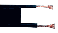
Twin-lead cable is a two-conductor flat cable used as a balanced transmission line to carry radio frequency (RF) signals. It is constructed of two stranded or solid copper or copper-clad steel wires, held a precise distance apart by a plastic ribbon. The uniform spacing of the wires is the key to the cable's function as a transmission line; any abrupt changes in spacing would reflect some of the signal back toward the source. The plastic also covers and insulates the wires. It is available with several different values of characteristic impedance, the most common type is 300 ohm.
Radiation resistance is that part of an antenna's feedpoint electrical resistance caused by the emission of radio waves from the antenna. A radio transmitter excites with a radio frequency alternating current an antenna, which radiates the exciting energy as radio waves. Because the antenna is absorbing the energy it is radiating from the transmitter, the antenna's input terminals present a resistance to the current from the transmitter.

The Tilted Terminated Folded Dipole or Balanced Termination, Folded Dipole (BTFD) - also known as W3HH antenna - is a general-purpose shortwave antenna developed in the late 1940s by the United States Navy. It performs reasonably well over a broad frequency range, without marked dead spots in terms of either frequency, direction, or angle of radiation above the horizon.

In radio and telecommunications a dipole antenna or doublet is the simplest and most widely used class of antenna. The dipole is any one of a class of antennas producing a radiation pattern approximating that of an elementary electric dipole with a radiating structure supporting a line current so energized that the current has only one node at each end. A dipole antenna commonly consists of two identical conductive elements such as metal wires or rods. The driving current from the transmitter is applied, or for receiving antennas the output signal to the receiver is taken, between the two halves of the antenna. Each side of the feedline to the transmitter or receiver is connected to one of the conductors. This contrasts with a monopole antenna, which consists of a single rod or conductor with one side of the feedline connected to it, and the other side connected to some type of ground. A common example of a dipole is the "rabbit ears" television antenna found on broadcast television sets.

A whip antenna is an antenna consisting of a straight flexible wire or rod. The bottom end of the whip is connected to the radio receiver or transmitter. A whip antenna is a form of monopole antenna. The antenna is designed to be flexible so that it does not break easily, and the name is derived from the whip-like motion that it exhibits when disturbed. Whip antennas for portable radios are often made of a series of interlocking telescoping metal tubes, so they can be retracted when not in use. Longer whips, made for mounting on vehicles and structures, are made of a flexible fiberglass rod around a wire core and can be up to 11 m long.

An antenna tuner is a passive electronic device inserted into the feedline between a radio transmitter and its antenna. Its purpose is to optimize power transfer by matching the impedance of the radio to the signal impedance at the end of the feedline connecting the antenna to the transmitter.

A mast radiator is a radio mast or tower in which the metal structure itself is energized and functions as an antenna. This design, first used widely in the 1930s, is commonly used for transmitting antennas operating at low frequencies, in the LF and MF bands, in particular those used for AM radio broadcasting stations. The conductive steel mast is electrically connected to the transmitter. Its base is usually mounted on a nonconductive support to insulate it from the ground. A mast radiator is a form of monopole antenna.

A ‘T’-antenna, ‘T’-aerial, or flat-top antenna is a monopole radio antenna consisting of one or more horizontal wires suspended between two supporting radio masts or buildings and insulated from them at the ends. A vertical wire is connected to the center of the horizontal wires and hangs down close to the ground, connected to the transmitter or receiver. The shape of the antenna resembles the letter "T", hence the name. The transmitter power is applied, or the receiver is connected, between the bottom of the vertical wire and a ground connection.

The J-pole antenna, more properly known as the J antenna, is a vertical omnidirectional transmitting antenna used in the shortwave frequency bands. It was invented by Hans Beggerow in 1909 for use in Zeppelin airships. Trailed behind the airship, it consisted of a single one half wavelength long wire radiator, in series with a quarter-wave parallel transmission line tuning stub that matches the antenna impedance to the feedline. By 1936 this antenna began to be used for land-based transmitters with the radiating element and the matching section mounted vertically, giving it the shape of the letter "J", and by 1943 it was named the J antenna. When the radiating half-wave section is mounted horizontally, at right-angles to the quarter-wave matching stub, the variation is usually called a Zepp antenna.
A loop antenna is a radio antenna consisting of a loop or coil of wire, tubing, or other electrical conductor, that for transmitting is usually fed by a balanced power source or for receiving feeds a balanced load. Within this physical description there are two distinct types:

A monopole antenna is a class of radio antenna consisting of a straight rod-shaped conductor, often mounted perpendicularly over some type of conductive surface, called a ground plane. The driving signal from the transmitter is applied, or for receiving antennas the output signal to the receiver is taken, between the lower end of the monopole and the ground plane. One side of the antenna feedline is attached to the lower end of the monopole, and the other side is attached to the ground plane, which is often the Earth. This contrasts with a dipole antenna which consists of two identical rod conductors, with the signal from the transmitter applied between the two halves of the antenna.
A radio transmitter or receiver is connected to an antenna which emits or receives the radio waves. The antenna feed system or antenna feed is the cable or conductor, and other associated equipment, which connects the transmitter or receiver with the antenna and makes the two devices compatible. In a radio transmitter, the transmitter generates an alternating current of radio frequency, and the feed system feeds the current to the antenna, which converts the power in the current to radio waves. In a radio receiver, the incoming radio waves excite tiny alternating currents in the antenna, and the feed system delivers this current to the receiver, which processes the signal.
In RF engineering, radial has three distinct meanings, both referring to lines which radiate from a radio antenna, but neither meaning is related to the other.

The folded unipole antenna is a type of monopole mast radiator antenna used as a transmitting antenna mainly in the medium wave band for AM radio broadcasting stations. It consists of a vertical metal rod or mast mounted over and connected at its base to a grounding system consisting of buried wires. The mast is surrounded by a "skirt" of vertical wires electrically attached at or near the top of the mast. The skirt wires are connected by a metal ring near the mast base, and the feedline feeding power from the transmitter is connected between the ring and the ground.

An umbrella antenna is a capacitively top-loaded wire monopole antenna, consisting in most cases of a mast fed at the ground end, to which a number of radial wires are connected at the top, sloping downwards. One side of the feedline supplying power from the transmitter is connected to the mast, and the other side to a ground (Earthing) system of radial wires buried in the earth under the antenna. They are used as transmitting antennas below 1 MHz, in the MF, LF and particularly the VLF bands, at frequencies sufficiently low that it is impractical or infeasible to build a full size quarter-wave monopole antenna. The outer end of each radial wire, sloping down from the top of the antenna, is connected by an insulator to a supporting rope or cable anchored to the ground; the radial wires can also support the mast as guy wires. The radial wires make the antenna look like the wire frame of a giant umbrella hence the name.
A shortwave broadband antenna is a radio antenna that can be used for transmission of any shortwave radio band from among the greater part of the shortwave radio spectrum, without requiring any band-by-band adjustment of the antenna. Generally speaking, there is no difficulty in building an adequate receiving antenna; the challenge is designing an antenna which can be used for transmission without an adjustable impedance matching network.

The G5RV antenna is a dipole with a symmetric resonant feeder line, which serves as impedance matcher for a 50 Ω coax cable to the transceiver.
In radio systems, many different antenna types are used whose properties are especially crafted for particular applications. Antennas can be classified in various ways. The list below groups together antennas under common operating principles, following the way antennas are classified in many engineering textbooks.


