SPICE is a general-purpose, open-source analog electronic circuit simulator. It is a program used in integrated circuit and board-level design to check the integrity of circuit designs and to predict circuit behavior.
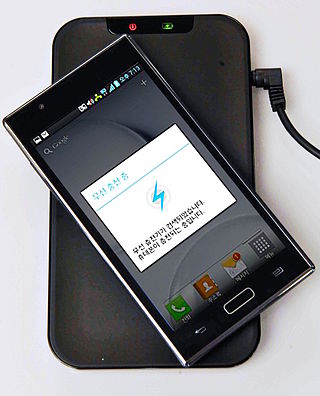
Wireless power transfer (WPT), wireless power transmission, wireless energy transmission (WET), or electromagnetic power transfer is the transmission of electrical energy without wires as a physical link. In a wireless power transmission system, an electrically powered transmitter device generates a time-varying electromagnetic field that transmits power across space to a receiver device; the receiver device extracts power from the field and supplies it to an electrical load. The technology of wireless power transmission can eliminate the use of the wires and batteries, thereby increasing the mobility, convenience, and safety of an electronic device for all users. Wireless power transfer is useful to power electrical devices where interconnecting wires are inconvenient, hazardous, or are not possible.

A magnetic bearing is a type of bearing that supports a load using magnetic levitation. Magnetic bearings support moving parts without physical contact. For instance, they are able to levitate a rotating shaft and permit relative motion with very low friction and no mechanical wear. Magnetic bearings support the highest speeds of any kind of bearing and have no maximum relative speed.

A magnetic circuit is made up of one or more closed loop paths containing a magnetic flux. The flux is usually generated by permanent magnets or electromagnets and confined to the path by magnetic cores consisting of ferromagnetic materials like iron, although there may be air gaps or other materials in the path. Magnetic circuits are employed to efficiently channel magnetic fields in many devices such as electric motors, generators, transformers, relays, lifting electromagnets, SQUIDs, galvanometers, and magnetic recording heads.
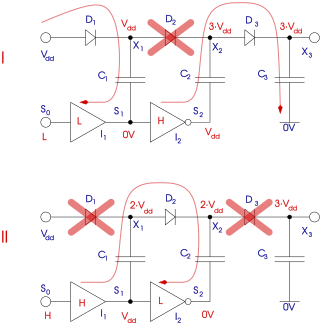
A charge pump is a kind of DC-to-DC converter that uses capacitors for energetic charge storage to raise or lower voltage. Charge-pump circuits are capable of high efficiencies, sometimes as high as 90–95%, while being electrically simple circuits.
This is an alphabetical list of articles pertaining specifically to electrical and electronics engineering. For a thematic list, please see List of electrical engineering topics. For a broad overview of engineering, see List of engineering topics. For biographies, see List of engineers.

Computational electromagnetics (CEM), computational electrodynamics or electromagnetic modeling is the process of modeling the interaction of electromagnetic fields with physical objects and the environment using computers.
Feko is a computational electromagnetics software product developed by Altair Engineering. The name is derived from the German acronym "Feldberechnung für Körper mit beliebiger Oberfläche", which can be translated as "field calculations involving bodies of arbitrary shape". It is a general purpose 3D electromagnetic (EM) simulator.

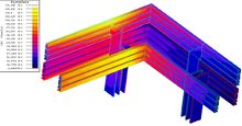
Partial element equivalent circuit method (PEEC) is partial inductance calculation used for interconnect problems from early 1970s which is used for numerical modeling of electromagnetic (EM) properties. The transition from a design tool to the full-wave method involves the capacitance representation, the inclusion of time retardation and the dielectric formulation. Using the PEEC method, the problem will be transferred from the electromagnetic domain to the circuit domain where conventional SPICE-like circuit solvers can be employed to analyze the equivalent circuit. By having the PEEC model one can easily include any electrical component e.g. passive components, sources, non-linear elements, ground, etc. to the model. Moreover, using the PEEC circuit, it is easy to exclude capacitive, inductive or resistive effects from the model when it is possible, in order to make the model smaller. As an example, in many applications within power electronics, the magnetic field is a dominating factor over the electric field due to the high current in the systems. Therefore, the model can be simplified by just neglecting capacitive couplings in the model which can simply be done by excluding the capacitors from the PEEC model.

The gyrator–capacitor model - sometimes also the capacitor-permeance model - is a lumped-element model for magnetic circuits, that can be used in place of the more common resistance–reluctance model. The model makes permeance elements analogous to electrical capacitance rather than electrical resistance. Windings are represented as gyrators, interfacing between the electrical circuit and the magnetic model.
The space mapping methodology for modeling and design optimization of engineering systems was first discovered by John Bandler in 1993. It uses relevant existing knowledge to speed up model generation and design optimization of a system. The knowledge is updated with new validation information from the system when available.
A loss free resistor (LFR) is a resistor that does not lose energy. The first implementation was due to Singer and it has been implemented in various settings.
This glossary of electrical and electronics engineering is a list of definitions of terms and concepts related specifically to electrical engineering and electronics engineering. For terms related to engineering in general, see Glossary of engineering.
Slobodan Ćuk is a Serbian author, inventor, business owner, electrical engineer, and professor of electrical engineering at the California Institute of Technology (Caltech). The Ćuk switched-mode DC-to-DC voltage converter is named after him.
Electromagnetically induced acoustic noise, electromagnetically excited acoustic noise, or more commonly known as coil whine, is audible sound directly produced by materials vibrating under the excitation of electromagnetic forces. Some examples of this noise include the mains hum, hum of transformers, the whine of some rotating electric machines, or the buzz of fluorescent lamps. The hissing of high voltage transmission lines is due to corona discharge, not magnetism.
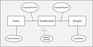
Conducted emissions are the effects in power quality that occur via electrical and magnetic coupling, electronic switch of semiconductor devices, which form a part of electromagnetic compatibility issues in electrical engineering. These affect the ability of all interconnected system devices in the electromagnetic environment, by restricting or limiting their intentional generation, propagation and reception of electromagnetic energy.
The black box model of power converter also called behavior model, is a method of system identification to represent the characteristics of power converter, that is regarded as a black box. There are two types of black box model of power converter - when the model includes the load, it is called terminated model, otherwise un-terminated model. The type of black box model of power converter is chosen based on the goal of modeling. This black box model of power converter could be a tool for filter design of a system integrated with power converters.
Switching Control Techniques address electromagnetic interference (EMI) mitigation on power electronics (PE). The design of power electronics involves overcoming three key challenges:
- power losses
- EMI
- harmonics
Signal Transition Graphs (STGs) are typically used in electronic engineering and computer engineering to describe dynamic behaviour of asynchronous circuits, for the purposes of their analysis or synthesis.

SPICE OPUS is a free general purpose electronic circuit simulator, developed and maintained by members of EDA Group, University of Ljubljana, Slovenia. It is based on original Berkeley’s SPICE analog circuit simulator and includes various improvements and advances, such as memory-leak bug fixes and plotting tool improvements. SPICE OPUS is specially designed for fast optimization loops via its built-in optimizer.