A backplane or backplane system is a group of electrical connectors in parallel with each other, so that each pin of each connector is linked to the same relative pin of all the other connectors, forming a computer bus. It is used to connect several printed circuit boards together to make up a complete computer system. Backplanes commonly use a printed circuit board, but wire-wrapped backplanes have also been used in minicomputers and high-reliability applications.

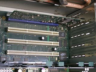
Industry Standard Architecture (ISA) is the 16-bit internal bus of IBM PC/AT and similar computers based on the Intel 80286 and its immediate successors during the 1980s. The bus was (largely) backward compatible with the 8-bit bus of the 8088-based IBM PC, including the IBM PC/XT as well as IBM PC compatibles.

Small Computer System Interface is a set of standards for physically connecting and transferring data between computers and peripheral devices, best known for its use with storage devices such as hard disk drives. SCSI was introduced in the 1980s and has seen widespread use on servers and high-end workstations, with new SCSI standards being published as recently as SAS-4 in 2017.

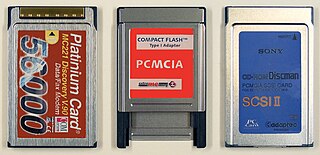
PC Card is a parallel peripheral interface for laptop computers and PDAs. The PCMCIA originally introduced the 16-bit ISA-based PCMCIA Card in 1990, but renamed it to PC Card in March 1995 to avoid confusion with the name of the organization. The CardBus PC Card was introduced as a 32-bit version of the original PC Card, based on the PCI specification. The card slots are backward compatible for the original 16-bit card, older slots are not forward compatible with newer cards.

In computing, an expansion card is a printed circuit board that can be inserted into an electrical connector, or expansion slot on a computer's motherboard to add functionality to a computer system. Sometimes the design of the computer's case and motherboard involves placing most of these slots onto a separate, removable card. Typically such cards are referred to as a riser card in part because they project upward from the board and allow expansion cards to be placed above and parallel to the motherboard.
Internet Small Computer Systems Interface or iSCSI is an Internet Protocol-based storage networking standard for linking data storage facilities. iSCSI provides block-level access to storage devices by carrying SCSI commands over a TCP/IP network. iSCSI facilitates data transfers over intranets and to manage storage over long distances. It can be used to transmit data over local area networks (LANs), wide area networks (WANs), or the Internet and can enable location-independent data storage and retrieval.

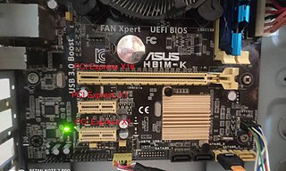
PCI Express, officially abbreviated as PCIe or PCI-e, is a high-speed serial computer expansion bus standard, designed to replace the older PCI, PCI-X and AGP bus standards. It is the common motherboard interface for personal computers' graphics cards, capture cards, sound cards, hard disk drive host adapters, SSDs, Wi-Fi, and Ethernet hardware connections. PCIe has numerous improvements over the older standards, including higher maximum system bus throughput, lower I/O pin count and smaller physical footprint, better performance scaling for bus devices, a more detailed error detection and reporting mechanism, and native hot-swap functionality. More recent revisions of the PCIe standard provide hardware support for I/O virtualization.

SATA is a computer bus interface that connects host bus adapters to mass storage devices such as hard disk drives, optical drives, and solid-state drives. Serial ATA succeeded the earlier Parallel ATA (PATA) standard to become the predominant interface for storage devices.

In computer hardware a host controller, host adapter or host bus adapter (HBA) connects a computer system bus which acts as the host system to other network and storage devices. The terms are primarily used to refer to devices for connecting SCSI, SAS, NVMe, Fibre Channel and SATA devices. Devices for connecting to FireWire, USB and other devices may also be called host controllers or host adapters.

Small Form-factor Pluggable (SFP) is a compact, hot-pluggable network interface module format used for both telecommunication and data communications applications. An SFP interface on networking hardware is a modular slot for a media-specific transceiver, such as for a fiber-optic cable or a copper cable. The advantage of using SFPs compared to fixed interfaces is that individual ports can be equipped with different types of transceivers as required, with the majority including optical line terminals, network cards, switches and routers.

PCI-X, short for Peripheral Component Interconnect eXtended, is a computer bus and expansion card standard that enhances the 32-bit PCI local bus for higher bandwidth demanded mostly by servers and workstations. It uses a modified protocol to support higher clock speeds, but is otherwise similar in electrical implementation. PCI-X 2.0 added speeds up to 533 MHz, with a reduction in electrical signal levels.

In computing, Serial Attached SCSI (SAS) is a point-to-point serial protocol that moves data to and from computer-storage devices such as hard disk drives and tape drives. SAS replaces the older Parallel SCSI bus technology that first appeared in the mid-1980s. SAS, like its predecessor, uses the standard SCSI command set. SAS offers optional compatibility with Serial ATA (SATA), versions 2 and later. This allows the connection of SATA drives to most SAS backplanes or controllers. The reverse, connecting SAS drives to SATA backplanes, is not possible.
HPE Integrity Servers is a series of server computers produced by Hewlett Packard Enterprise since 2003, based on the Itanium processor. The Integrity brand name was inherited by HP from Tandem Computers via Compaq.

USB On-The-Go is a specification first used in late 2001 that allows USB devices, such as tablets or smartphones, to also act as a host, allowing other USB devices, such as USB flash drives, digital cameras, mouse or keyboards, to be attached to them. Use of USB OTG allows devices to switch back and forth between the roles of host and device. For example, a smartphone may read from removable media as the host device, but present itself as a USB Mass Storage Device when connected to a host computer.
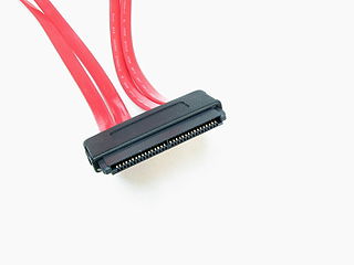
A SCSI connector is used to connect computer parts that communicate with each other via the SCSI standard. Generally, two connectors, designated male and female, plug together to form a connection which allows two components, such as a computer and a disk drive, to communicate with each other. SCSI connectors can be electrical connectors or optical connectors. There have been a large variety of SCSI connectors in use at one time or another in the computer industry. Twenty-five years of evolution and three major revisions of the standards resulted in requirements for Parallel SCSI connectors that could handle an 8, 16 or 32 bit wide bus running at 5, 10 or 20 megatransfer/s, with conventional or differential signaling. Serial SCSI added another three transport types, each with one or more connector types. Manufacturers have frequently chosen connectors based on factors of size, cost, or convenience at the expense of compatibility.

Parallel SCSI is the earliest of the interface implementations in the SCSI family. SPI is a parallel bus; there is one set of electrical connections stretching from one end of the SCSI bus to the other. A SCSI device attaches to the bus but does not interrupt it. Both ends of the bus must be terminated.
Serial general-purpose input/output (SGPIO) is a four-signal bus used between a host bus adapter (HBA) and a backplane. Of the four signals, three are driven by the HBA and one by the backplane. Typically, the HBA is a storage controller located inside a server, desktop, rack or workstation computer that interfaces with hard disk drives or solid-state drives to store and retrieve data. It is considered an extension of the general-purpose input/output (GPIO) concept. – The SGPIO specification is maintained by the Small Form Factor Committee in the SFF-8485 standard. The International Blinking Pattern Interpretation indicates how SGPIO signals are interpreted into blinking light-emitting diodes (LEDs) on disk arrays and storage back-planes.
The introduction of Serial Attached SCSI (SAS) as the most recent evolution of SCSI required redefining the related standard for enclosure management, called SCSI Enclosure Services. SES-2, or SCSI Enclosure Management 2 first revision, was introduced in 2002 and is now at revision 20. SES-2 SCSI Enclosure Services (SES) permit the management and sense the state of power supplies, cooling devices, LED displays, indicators, individual drives, and other non-SCSI elements installed in an enclosure. SES2 alerts users about drive, temperature and fan failures with an audible alarm and a fan failure LED.
CompactPCI Serial is an industrial standard for modular computer systems. It is based on the established PICMG 2.0 CompactPCI standard, which uses the parallel PCI bus for communication among a system's card components. In contrast to this, CompactPCI Serial uses only serial point-to-point connections. CompactPCI Serial was officially adopted by the PCI Industrial Computer Manufacturers Group PICMG as PICMG CPCI-S.0 CompactPCI Serial in March 2011. Its mechanical concept is based on the proven standards of IEEE 1101-1-1998 and IEEE 1101-10-1996. CompactPCI Serial includes different connectors that permit very high data rates. The new technology standard succeeding parallel CompactPCI comprises another specification called PICMG 2.30 CompactPCI PlusIO. This is why CompactPCI Serial and CompactPCI PlusIO as a whole were also called CompactPCI Plus. PICMG's first working title of CompactPCI Serial was CPLUS.0. CompactPCI Serial backplanes and chassis are developed by Schroff, Elmа, and Pixus Technologies companies, as for the CompactPCI Serial board level electronics – they are developed by MEN Mikro Elektronik, Fastwel, EKF, Emerson Embedded Computing, ADLINK, and Kontron.

SATA Express is a computer bus interface that supports both Serial ATA (SATA) and PCI Express (PCIe) storage devices, initially standardized in the SATA 3.2 specification. The SATA Express connector used on the host side is backward compatible with the standard SATA data connector, while it also provides two PCI Express lanes as a pure PCI Express connection to the storage device.


