John J. Uicker

Last updated
John J. Uicker
Prof.John J.Uicker.jpg
John J. Uicker, Jr. 2013
Born
John J. Uicker, Jr.

(1938-07-11)July 11, 1938
East Derry, New Hampshire
DiedApril 25, 2023(2023-04-25) (aged 84)
Madison, Wisconsin
NationalityAmerican
Alma materUniversity of Detroit and Northwestern University
Known for4 X 4 Matrix Method Mechanism analysis Sheth-Uicker Notation for mechanism
Scientific career
FieldsEngineering, Kinematics and Kinetics
Institutions University of Wisconsin-Madison
Doctoral advisor Jacques Denavit

John J. Uicker, Jr was a professor of mechanical engineering at the University of Wisconsin-Madison, Wisconsin from 1967 to 2007 and professor emeritus from 2007 until his death in 2023. [1] [2]

Contents

Education

Uicker received his BME degree from the University of Detroit, and his MS and PhD degrees in mechanical engineering from Northwestern University. [3] During his education, Uicker joined the engineering honor societies Pi Tau Sigma and Sigma Xi. He developed the (4x4) matrix method for kinematic analysis as part of his doctoral research. Following his education, Uicker served two years in the US Army Metrology and Calibration Center at the Frankford Arsenal in Philadelphia, PA. He received a certificate of commendation from the Army for his historically significant paper on "Dynamic Force Analysis of Spatial Linkages." [4] [5]

He joined the University of Wisconsin faculty in 1967, where he served until his retirement in 2007. In this role, he became the pioneering researcher on transformation matrix methods of linkage analysis, and was the first to advise on their use in the dynamics of mechanical systems. In 1969, he was awarded the Ralph R Teetor Educational Fund Award of the Society of Automotive Engineers at Detroit, MI. As an ASEE resident fellow, Uicker spent 1972–73 at Ford Motor Company. He was also awarded a Fulbright-Hayes Senior Lectureship and became a visiting professor at Cranfield Institute of Technology in Cranfield, England, in 1978–79. [6]

Career

Throughout his career, his teaching and research focused on solid geometric modeling and the modeling of mechanical motion, and their application to computer-aided design and manufacturing, including kinematics, dynamics, and simulation of articulated rigid-body mechanical systems. He advised numerous masters and doctoral students during his tenure at the UW and was twice awarded for distinguished teaching.

Uicker coined the 4 X 4 matrix method for kinematic analysis of linkages in 1964. [7] This provided, for the first time, a numerical method for the position solution of spatial linkages. He proposed the Sheth-Uicker Notation for kinematic analysis of mechanical linkages in 1971 which remedied ambiguities in the Denavit-Hartenberg notation method. [8]

Involvement in professional associations was important to Uicker's growth and recognition in his field. He served on several national committees of The American Society of Mechanical Engineers (ASME] and the Society of Automotive Engineers (SAE). He received the ASME Mechanisms Committee Award in 2004 and was named ASME Fellow in 2007. He is a founding member of the U.S. Council on the Theory of Mechanism and Machine Science [9] and of the International Federation of Mechanism and Machine Science (IFToMM). [10] He served as editor-in-chief of the Mechanism and Machine Theory journal of the federation from 1973 to 1978. He was a registered mechanical engineer in Wisconsin for over 50 years and served for many years as an active consultant to industry. Uicker was a fellow of the American Society of Mechanical Engineers and was awarded the Mechanisms and Robotics Committee Award for his many years of service on the committee. He also served on the Computational Geometry Committee and the Design Automation Committee. [6]

Uicker was instrumental in initiating a new era of computing for education on the University of Wisconsin-Madison campus. He founded their Computer Aided Engineering Center and served as director for its initial ten years of operation. Using these facilities, Uicker and his students developed a number of geometric modeling and computer-aided design techniques for the simulation of solidification in metal castings, which made manufacturing more predictable and cost-effective. With funding from the National Science Foundation and contributions from the UW and Ford Motor Company, Uicker's research program developed a computer software system called the Integrated Mechanisms Program (IMP). [11] This was the first generalized software system for the kinematic, static, and dynamic simulation of rigid body mechanical systems such as robots and automotive suspensions. His solid modeling software system was known as Geometric Modeling of Solids (GMOS). These concepts were extended to the analysis of solidification in metal castings with a software application known as SWIFT. All of these programs supported industry automation and were utilized by hundreds of companies across the US and even around the world.[ citation needed ]

Works

Related Research Articles

<span class="mw-page-title-main">Machine</span> Powered mechanical device

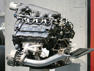
A machine is a physical system using power to apply forces and control movement to perform an action. The term is commonly applied to artificial devices, such as those employing engines or motors, but also to natural biological macromolecules, such as molecular machines. Machines can be driven by animals and people, by natural forces such as wind and water, and by chemical, thermal, or electrical power, and include a system of mechanisms that shape the actuator input to achieve a specific application of output forces and movement. They can also include computers and sensors that monitor performance and plan movement, often called mechanical systems.

The term ideal machine refers to a hypothetical mechanical system in which energy and power are not lost or dissipated through friction, deformation, wear, or other inefficiencies. Ideal machines have the theoretical maximum performance, and therefore are used as a baseline for evaluating the performance of real machine systems.

<span class="mw-page-title-main">Inverse kinematics</span> Computing joint values of a kinematic chain from a known end position

In computer animation and robotics, inverse kinematics is the mathematical process of calculating the variable joint parameters needed to place the end of a kinematic chain, such as a robot manipulator or animation character's skeleton, in a given position and orientation relative to the start of the chain. Given joint parameters, the position and orientation of the chain's end, e.g. the hand of the character or robot, can typically be calculated directly using multiple applications of trigonometric formulas, a process known as forward kinematics. However, the reverse operation is, in general, much more challenging.

<span class="mw-page-title-main">Linkage (mechanical)</span> Assembly of systems connected to manage forces and movement

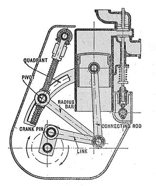
A mechanical linkage is an assembly of systems connected to manage forces and movement. The movement of a body, or link, is studied using geometry so the link is considered to be rigid. The connections between links are modeled as providing ideal movement, pure rotation or sliding for example, and are called joints. A linkage modeled as a network of rigid links and ideal joints is called a kinematic chain.

In physics, the degrees of freedom (DOF) of a mechanical system is the number of independent parameters that define its configuration or state. It is important in the analysis of systems of bodies in mechanical engineering, structural engineering, aerospace engineering, robotics, and other fields.

<span class="mw-page-title-main">Overconstrained mechanism</span> Moveable linkage with zero mobility

In mechanical engineering, an overconstrained mechanism is a linkage that has more degrees of freedom than is predicted by the mobility formula. The mobility formula evaluates the degree of freedom of a system of rigid bodies that results when constraints are imposed in the form of joints between the links.

<span class="mw-page-title-main">Forward kinematics</span> Computing a robots end-effector position from joint values and kinematic equations

In robot kinematics, forward kinematics refers to the use of the kinematic equations of a robot to compute the position of the end-effector from specified values for the joint parameters.

<span class="mw-page-title-main">Kinematic diagram</span> Representation of the connectivity of a mechanisms links and joints

In mechanical engineering, a kinematic diagram or kinematic scheme illustrates the connectivity of links and joints of a mechanism or machine rather than the dimensions or shape of the parts. Often links are presented as geometric objects, such as lines, triangles or squares, that support schematic versions of the joints of the mechanism or machine.

In classical mechanics, a kinematic pair is a connection between two physical objects that imposes constraints on their relative movement (kinematics). German engineer Franz Reuleaux introduced the kinematic pair as a new approach to the study of machines that provided an advance over the motion of elements consisting of simple machines.

<span class="mw-page-title-main">Kinematic chain</span> Mathematical model for a mechanical system

In mechanical engineering, a kinematic chain is an assembly of rigid bodies connected by joints to provide constrained motion that is the mathematical model for a mechanical system. As the word chain suggests, the rigid bodies, or links, are constrained by their connections to other links. An example is the simple open chain formed by links connected in series, like the usual chain, which is the kinematic model for a typical robot manipulator.

There are many conventions used in the robotics research field. This article summarises these conventions.

<span class="mw-page-title-main">Denavit–Hartenberg parameters</span> Convention for attaching reference frames to links of a kinematic chain

In mechanical engineering, the Denavit–Hartenberg parameters are the four parameters associated with a particular convention for attaching reference frames to the links of a spatial kinematic chain, or robot manipulator.

The Chebychev–Grübler–Kutzbach criterion determines the number of degrees of freedom of a kinematic chain, that is, a coupling of rigid bodies by means of mechanical constraints. These devices are also called linkages.

<span class="mw-page-title-main">Mechanism (engineering)</span> Device used to transfer forces via non-electric means

In engineering, a mechanism is a device that transforms input forces and movement into a desired set of output forces and movement. Mechanisms generally consist of moving components which may include:

The Mechanisms and Robotics Award is an honor that is given annually by the Mechanisms and Robotics Committee of the American Society of Mechanical Engineers (ASME), to engineers known for a lifelong contribution to the field of mechanism design or theory. This prestigious honor can only be given once to any individual.

Kinematics equations are the constraint equations of a mechanical system such as a robot manipulator that define how input movement at one or more joints specifies the configuration of the device, in order to achieve a task position or end-effector location. Kinematics equations are used to analyze and design articulated systems ranging from four-bar linkages to serial and parallel robots.

<span class="mw-page-title-main">Nils Otto Myklestad</span> American engineer and professor (1909–1972)

Nils Otto Myklestad was an American mechanical engineer and engineering professor. An authority on mechanical vibration, he was employed by a number of important US engineering firms and served on the faculty of several major engineering universities. Myklestad made significant contributions to both engineering practice and engineering education, publishing a number of widely influential technical journal papers and textbooks. He also was granted five US patents during his career.

<span class="mw-page-title-main">Dwell mechanism</span> Intermittent motion mechanism

A dwell mechanism is an intermittent motion mechanism that alternates forward and return motion with holding position(s).

<span class="mw-page-title-main">Leg mechanism</span> Mechanical system that walks

A leg mechanism is a mechanical system designed to provide a propulsive force by intermittent frictional contact with the ground. This is in contrast with wheels or continuous tracks which are intended to maintain continuous frictional contact with the ground. Mechanical legs are linkages that can have one or more actuators, and can perform simple planar or complex motion. Compared to a wheel, a leg mechanism is potentially better fitted to uneven terrain, as it can step over obstacles.

In mechanical engineering, kinematic synthesis determines the size and configuration of mechanisms that shape the flow of power through a mechanical system, or machine, to achieve a desired performance. The word synthesis refers to combining parts to form a whole. Hartenberg and Denavit describe kinematic synthesis as

...it is design, the creation of something new. Kinematically, it is the conversion of a motion idea into hardware.

References

  1. "Uicker, John - UW-Engineering Directory | College of Engineering @ The University of Wisconsin-Madison".
  2. Scott, Caitlin (2023-05-03). "Obituary: Mechanical Engineering's John J. Uicker, Jr". College of Engineering - University of Wisconsin-Madison. Retrieved 2023-05-17.
  3. "Class Notes: McCormick Magazine: Northwestern University: McCormick School of Engineering". www.mccormick.northwestern.edu. Archived from the original on 2012-07-25.
  4. "Army Honors UW Professor". The Capital Times. 3 Nov 1967. p. 10.
  5. Uicker, John Jr. Dynamic Force Analysis of Spatial Linkages, ASME Journal of Applied Mechanics, Series E, Vol. 34, No.2, pp. 418-424, June 1967
  6. 1 2 Uicker, John Jr; Pennock, Gordon; Shigley, Joseph (2017). Theory of Machines and Mechanisms (5th ed.). New York: Oxford University Press. pp. xxv. ISBN   9780190264482.{{cite book}}: CS1 maint: multiple names: authors list (link)
  7. J. J. Uicker, JR., J. Denavit, R. S.Hartengerg, "An iterative method for the Displacement Analysis of Spatial Mechanisms", Journal of Applied Mechanics, 1964 pp. 309-314.
  8. P.N. Sheth, J.J.Uicker, "A generalized Symbolic notation for mechanisms", Transactions of the ASME, vol.93, 1971, pp. 102-112.
  9. "(USCToMM)". Archived from the original on 2016-08-18. Retrieved 2016-07-20.
  10. "Home". Archived from the original on 2016-08-18. Retrieved 2016-07-20.
  11. P. N. Sheth, J. J. Uicker Jr., "IMP (Integrated Mechanisms Program), A Computer-Aided Design Analysis System for Mechanisms and Linkage", Transactions of the ASME, vol.94, 1972, pp. 454-464.