Kinematics is a subfield of physics, developed in classical mechanics, that describes the motion of points, bodies (objects), and systems of bodies without considering the forces that cause them to move. Kinematics, as a field of study, is often referred to as the "geometry of motion" and is occasionally seen as a branch of mathematics. A kinematics problem begins by describing the geometry of the system and declaring the initial conditions of any known values of position, velocity and/or acceleration of points within the system. Then, using arguments from geometry, the position, velocity and acceleration of any unknown parts of the system can be determined. The study of how forces act on bodies falls within kinetics, not kinematics. For further details, see analytical dynamics.
In classical mechanics, the parameters that define the configuration of a system are called generalized coordinates, and the space defined by these coordinates is called the configuration space of the physical system. It is often the case that these parameters satisfy mathematical constraints, such that the set of actual configurations of the system is a manifold in the space of generalized coordinates. This manifold is called the configuration manifold of the system. Notice that this is a notion of "unrestricted" configuration space, i.e. in which different point particles may occupy the same position. In mathematics, in particular in topology, a notion of "restricted" configuration space is mostly used, in which the diagonals, representing "colliding" particles, are removed.

In computer animation and robotics, inverse kinematics is the mathematical process of calculating the variable joint parameters needed to place the end of a kinematic chain, such as a robot manipulator or animation character's skeleton, in a given position and orientation relative to the start of the chain. Given joint parameters, the position and orientation of the chain's end, e.g. the hand of the character or robot, can typically be calculated directly using multiple applications of trigonometric formulas, a process known as forward kinematics. However, the reverse operation is, in general, much more challenging.

A flexure bearing is a category of flexure which is engineered to be compliant in one or more angular degrees of freedom. Flexure bearings are often part of compliant mechanisms. Flexure bearings serve much of the same function as conventional bearings or hinges in applications which require angular compliance. However, flexures require no lubrication and exhibit very low or no friction.

Ragdoll physics is a type of procedural animation used by physics engines, which is often used as a replacement for traditional static death animations in video games and animated films. As computers increased in power, it became possible to do limited real-time physical simulations, which made death animations more realistic.
A flexure is a flexible element engineered to be compliant in specific degrees of freedom. Flexures are a design feature used by design engineers for providing adjustment or compliance in a design.
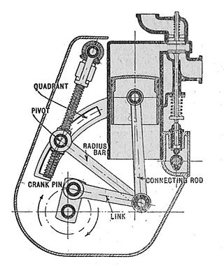
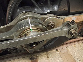
A mechanical linkage is an assembly of systems connected to manage forces and movement. The movement of a body, or link, is studied using geometry so the link is considered to be rigid. The connections between links are modeled as providing ideal movement, pure rotation or sliding for example, and are called joints. A linkage modeled as a network of rigid links and ideal joints is called a kinematic chain.
In physics, the degrees of freedom (DOF) of a mechanical system is the number of independent parameters that define its configuration or state. It is important in the analysis of systems of bodies in mechanical engineering, structural engineering, aerospace engineering, robotics, and other fields.

A cycloidal gear is a toothed gear with a cycloidal profile. Such gears are used in mechanical clocks and watches, rather than the involute gear form used for most other gears. Cycloidal gears have advantages over involute gears in such applications in being able to be produced flat, and having fewer points of contact.

A mirror mount is a device that holds a mirror. In optics research, these can be quite sophisticated devices, due to the need to be able to tip and tilt the mirror by controlled amounts, while still holding it in a precise position when it is not being adjusted.
In mechanical engineering, an overconstrained mechanism is a linkage that has more degrees of freedom than is predicted by the mobility formula. The mobility formula evaluates the degree of freedom of a system of rigid bodies that results when constraints are imposed in the form of joints between the links.

A parallel manipulator is a mechanical system that uses several computer-controlled serial chains to support a single platform, or end-effector. Perhaps, the best known parallel manipulator is formed from six linear actuators that support a movable base for devices such as flight simulators. This device is called a Stewart platform or the Gough-Stewart platform in recognition of the engineers who first designed and used them.
Multibody system is the study of the dynamic behavior of interconnected rigid or flexible bodies, each of which may undergo large translational and rotational displacements.
In classical mechanics, a kinematic pair is a connection between two physical objects that imposes constraints on their relative movement (kinematics). German engineer Franz Reuleaux introduced the kinematic pair as a new approach to the study of machines that provided an advance over the motion of elements consisting of simple machines.

In mechanical engineering, a kinematic chain is an assembly of rigid bodies connected by joints to provide constrained motion that is the mathematical model for a mechanical system. As the word chain suggests, the rigid bodies, or links, are constrained by their connections to other links. An example is the simple open chain formed by links connected in series, like the usual chain, which is the kinematic model for a typical robot manipulator.
The Chebychev–Grübler–Kutzbach criterion determines the number of degrees of freedom of a kinematic chain, that is, a coupling of rigid bodies by means of mechanical constraints. These devices are also called linkages.

In engineering, a mechanism is a device that transforms input forces and movement into a desired set of output forces and movement. Mechanisms generally consist of moving components which may include:

A revolute joint is a one-degree-of-freedom kinematic pair used frequently in mechanisms and machines. The joint constrains the motion of two bodies to pure rotation along a common axis. The joint does not allow translation, or sliding linear motion, a constraint not shown in the diagram. Almost all assemblies of multiple moving bodies include revolute joints in their designs. Revolute joints are used in numerous applications such as door hinges, mechanisms, and other uni-axial rotation devices.
A mechanical joint is a section of a machine which is used to connect one or more mechanical part to another. Mechanical joints may be temporary or permanent; most types are designed to be disassembled. Most mechanical joints are designed to allow relative movement of these mechanical parts of the machine in one degree of freedom, and restrict movement in one or more others.
In mechanical engineering, kinematic synthesis determines the size and configuration of mechanisms that shape the flow of power through a mechanical system, or machine, to achieve a desired performance. The word synthesis refers to combining parts to form a whole. Hartenberg and Denavit describe kinematic synthesis as
...it is design, the creation of something new. Kinematically, it is the conversion of a motion idea into hardware.


