A high-voltage direct current (HVDC) electric power transmission system uses direct current (DC) for electric power transmission, in contrast with the more common alternating current (AC) transmission systems. Most HVDC links use voltages between 100 kV and 800 kV.

A rectifier is an electrical device that converts alternating current (AC), which periodically reverses direction, to direct current (DC), which flows in only one direction.

A Flexible Alternating Current Transmission System (FACTS) is a family of Power-Electronic based devices designed for use on an Alternating Current (AC) Transmission System to improve and control Power Flow and support Voltage. FACTs devices are alternatives to traditional electric grid solutions and improvements, where building additional Transmission Lines or Substation is not economically or logistically viable.
In Electrical Engineering, a static VAR compensator (SVC) is a set of electrical devices for providing fast-acting reactive power on high-voltage electricity transmission networks. SVCs are part of the flexible AC transmission system device family, regulating voltage, power factor, harmonics and stabilizing the system. A static VAR compensator has no significant moving parts. Prior to the invention of the SVC, power factor compensation was the preserve of large rotating machines such as synchronous condensers or switched capacitor banks.

The HVDC Volgograd–Donbass is a 475 kilometres (295 mi) long bipolar ±400 kV high voltage direct current powerline used for transmitting electric power from Volga Hydroelectric Station at Volgograd in Russia to Donbas in eastern Ukraine and vice versa.
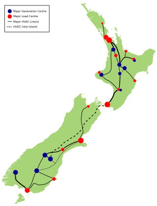
The HVDC Inter-Island link is a 610 km (380 mi) long, 1200 MW high-voltage direct current (HVDC) transmission system connecting the electricity networks of the North Island and South Island of New Zealand together. It is commonly referred to as the Cook Strait cable in the media and in press releases, although the link is much longer than its Cook Strait section. The link is owned and operated by state-owned transmission company Transpower New Zealand.

The Nelson River DC Transmission System, also known as the Manitoba Bipole, is an electric power transmission system of three high voltage, direct current lines in Manitoba, Canada, operated by Manitoba Hydro as part of the Nelson River Hydroelectric Project. It is now recorded on the list of IEEE Milestones in electrical engineering. Several records have been broken by successive phases of the project, including the largest mercury-arc valves, the highest DC transmission voltage and the first use of water-cooled thyristor valves in HVDC.

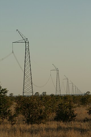
Cahora-Bassa is a separate bipolar HVDC power transmission line between the Cahora Bassa Hydroelectric Generation Station at the Cahora Bassa Dam in Mozambique, and Johannesburg, South Africa.

An HVDC converter station is a specialised type of substation which forms the terminal equipment for a high-voltage direct current (HVDC) transmission line. It converts direct current to alternating current or the reverse. In addition to the converter, the station usually contains:
The HVDC Itaipu is a High-voltage direct current overhead line transmission system in Brazil from the Itaipu hydroelectric power plant to the region of São Paulo. The project consists of two ±600 kV bipoles, each with a rated power of 3150 MW, which transmit power generated at 50 Hz from the Paraguay side of the Itaipu Dam to the Ibiúna converter station near São Roque, São Paulo. The system was put in service in several steps between 1984 and 1987, and remains among the most important HVDC installations in the world.

Path 27, also called the Intermountain or the Southern Transmission System (STS), is a high-voltage direct current (HVDC) electrical transmission line running from the coal-fired Intermountain Power Plant near Delta, Utah, to the Adelanto Converter Station at Adelanto, California, in the Southwestern United States. It was installed by Asea, a company based in Sweden, and commercialized in July 1986. The system is designed to carry power generated at the power plant in Utah to areas throughout Southern California. It is owned and operated by the Intermountain Power Agency, a cooperative consisting of six Los Angeles-area cities, the largest member being the Los Angeles Department of Water and Power (LADWP), and 29 smaller Utah municipalities.
The Eel River Converter Station is a high-voltage direct current (HVDC) converter station in Eel River Crossing, New Brunswick, Canada; it is the first operative HVDC station in the world equipped with thyristors.

In Electrical Engineering, a static synchronous compensator (STATCOM) is a shunt-connected, reactive compensation device used on transmission networks. It uses power electronics to form a voltage-source converter that can act as either a source or sink of reactive AC power to an electricity network. It is a member of the FACTS family of devices.

Hydro-Québec's electricity transmission system is an international electric power transmission system centred in Quebec, Canada. The system pioneered the use of very high voltage 735-kilovolt (kV) alternating current (AC) power lines that link the population centres of Montreal and Quebec City to distant hydroelectric power stations like the Daniel-Johnson Dam and the James Bay Project in northwestern Quebec and the Churchill Falls Generating Station in Labrador.

GKK Etzenricht, an abbreviation of Gleichstromkurzkupplung Etzenricht, meaning Etzenricht HVDC-back-to-back station, was an HVDC back-to-back facility near Etzenricht in the district of Neustadt an der Waldnaab in Bavaria, Germany. It was built on the site of the Etzenricht substation, a 380 kV/220 kV/110 kV-substation, which went into service in 1970 and expanded afterwards several times. The facility was used between 1993 and 1995 for the exchange of power between Germany and the Czech Republic, operated by Bayernwerk AG.

The GK Dürnrohr was a high-voltage direct current back-to-back scheme west of Dürnrohr substation, which was used for the energy exchange between Austria and Czechoslovakia between 1983 and 1996. The installation is no longer in use.

The National Grid is the nationwide system of electric power transmission in New Zealand. The grid is owned, operated and maintained by Transpower New Zealand, a state-owned enterprise, although some lines are owned by local distribution companies and leased to Transpower. In total, the national grid contains 11,803 kilometres (7,334 mi) of high-voltage lines and 178 substations.
An HVDC converter converts electric power from high voltage alternating current (AC) to high-voltage direct current (HVDC), or vice versa. HVDC is used as an alternative to AC for transmitting electrical energy over long distances or between AC power systems of different frequencies. HVDC converters capable of converting up to two gigawatts (GW) and with voltage ratings of up to 900 kilovolts (kV) have been built, and even higher ratings are technically feasible. A complete converter station may contain several such converters in series and/or parallel to achieve total system DC voltage ratings of up to 1,100 kV.
The Rio Madeira HVDC system is a high-voltage direct current transmission system in Brazil, built to export power from new hydro power plants on the Madeira River in the Amazon Basin to the major load centres of southeastern Brazil. The system consists of two converter stations at Porto Velho in the state of Rondônia and Araraquara in São Paulo state, interconnected by two bipolar ±600 kV DC transmission lines with a capacity of 3,150 megawatts (4,220,000 hp) each. In addition to the converters for the two bipoles, the Porto Velho converter station also includes two 400 MW back-to-back converters to supply power to the local 230 kV AC system. Hence the total export capacity of the Porto Velho station is 7100 MW: 6300 MW from the two bipoles and 800 MW from the two back-to-back converters. When Bipole 1 commenced commercial operation in 2014, Rio Madeira became the world’s longest HVDC line, surpassing the Xiangjiaba–Shanghai system in China. According to the energy research organisation Empresa de Pesquisa Energética (EPE), the length of the line is 2,375 kilometres (1,476 mi).
The Xiangjiaba–Shanghai HVDC system is a ±800 kV, 6400 MW high-voltage direct current transmission system in China. The system was built to export hydro power from Xiangjiaba Dam in Sichuan province, to the major city of Shanghai. Built and owned by State Grid Corporation of China (SGCC), the system became the world’s largest-capacity HVDC system when it was completed in July 2010, although it has already been overtaken by the 7200 MW Jinping–Sunan HVDC scheme which was put into operation in December 2012. It also narrowly missed becoming the world’s first 800 kV HVDC line, with the first pole of the Yunnan–Guangdong project having been put into service 6 months earlier. It was also the world’s longest HVDC line when completed, although that record is also expected to be overtaken early in 2013 with the completion of the first bipole of the Rio Madeira project in Brazil.


