In electronics, the figures of merit of an amplifier are numerical measures that characterize its properties and performance. Figures of merit can be given as a list of specifications that include properties such as gain, bandwidth, noise and linearity, among others listed in this article. Figures of merit are important for determining the suitability of a particular amplifier for an intended use.

An amplifier, electronic amplifier or (informally) amp is an electronic device that can increase the magnitude of a signal. It is a two-port electronic circuit that uses electric power from a power supply to increase the amplitude of a signal applied to its input terminals, producing a proportionally greater amplitude signal at its output. The amount of amplification provided by an amplifier is measured by its gain: the ratio of output voltage, current, or power to input. An amplifier is defined as a circuit that has a power gain greater than one.
In signal processing, distortion is the alteration of the original shape of a signal. In communications and electronics it means the alteration of the waveform of an information-bearing signal, such as an audio signal representing sound or a video signal representing images, in an electronic device or communication channel.
In telecommunications, a third-order intercept point (IP3 or TOI) is a specific figure of merit associated with the more general third-order intermodulation distortion (IMD3), which is a measure for weakly nonlinear systems and devices, for example receivers, linear amplifiers and mixers. It is based on the idea that the device nonlinearity can be modeled using a low-order polynomial, derived by means of Taylor series expansion. The third-order intercept point relates nonlinear products caused by the third-order nonlinear term to the linearly amplified signal, in contrast to the second-order intercept point that uses second-order terms.
A low-noise amplifier (LNA) is an electronic component that amplifies a very low-power signal without significantly degrading its signal-to-noise ratio (SNR). Any electronic amplifier will increase the power of both the signal and the noise present at its input, but the amplifier will also introduce some additional noise. LNAs are designed to minimize that additional noise, by choosing special components, operating points, and circuit topologies. Minimizing additional noise must balance with other design goals such as power gain and impedance matching.
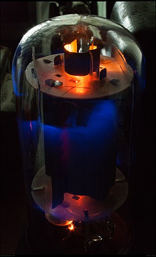
A valve amplifier or tube amplifier is a type of electronic amplifier that uses vacuum tubes to increase the amplitude or power of a signal. Low to medium power valve amplifiers for frequencies below the microwaves were largely replaced by solid state amplifiers in the 1960s and 1970s. Valve amplifiers can be used for applications such as guitar amplifiers, satellite transponders such as DirecTV and GPS, high quality stereo amplifiers, military applications and very high power radio and UHF television transmitters.

A push–pull amplifier is a type of electronic circuit that uses a pair of active devices that alternately supply current to, or absorb current from, a connected load. This kind of amplifier can enhance both the load capacity and switching speed.
Linear electronic oscillator circuits, which generate a sinusoidal output signal, are composed of an amplifier and a frequency selective element, a filter. A linear oscillator circuit which uses an RC network, a combination of resistors and capacitors, for its frequency selective part is called an RC oscillator.
In electronics, a frequency multiplier is an electronic circuit that generates an output signal and that output frequency is a harmonic (multiple) of its input frequency. Frequency multipliers consist of a nonlinear circuit that distorts the input signal and consequently generates harmonics of the input signal. A subsequent bandpass filter selects the desired harmonic frequency and removes the unwanted fundamental and other harmonics from the output.

A class-D amplifier or switching amplifier is an electronic amplifier in which the amplifying devices operate as electronic switches, and not as linear gain devices as in other amplifiers. They operate by rapidly switching back and forth between the supply rails, using pulse-width modulation, pulse-density modulation, or related techniques to produce a pulse train output. A simple low-pass filter may be used to attenuate their high-frequency content to provide analog output current and voltage. Little energy is dissipated in the amplifying transistors because they are always either fully on or fully off, so efficiency can exceed 90%.
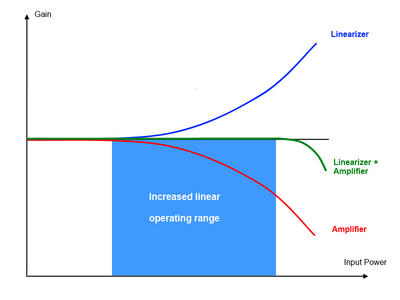
A linear amplifier is an electronic circuit whose output is proportional to its input, but capable of delivering more power into a load. The term usually refers to a type of radio-frequency (RF) power amplifier, some of which have output power measured in kilowatts, and are used in amateur radio. Other types of linear amplifier are used in audio and laboratory equipment. Linearity refers to the ability of the amplifier to produce signals that are accurate copies of the input. A linear amplifier responds to different frequency components independently, and tends not to generate harmonic distortion or intermodulation distortion. No amplifier can provide perfect linearity however, because the amplifying devices—transistors or vacuum tubes—follow nonlinear transfer function and rely on circuitry techniques to reduce those effects. There are a number of amplifier classes providing various trade-offs between implementation cost, efficiency, and signal accuracy.

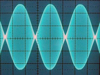
Clipping is a form of waveform distortion that occurs when an amplifier is overdriven and attempts to deliver an output voltage or current beyond its maximum capability. Driving an amplifier into clipping may cause it to output power in excess of its power rating.
Gain compression is a reduction in differential or slope gain caused by nonlinearity of the transfer function of an amplifying device for large-signal inputs.

Distortion and overdrive are forms of audio signal processing used to alter the sound of amplified electric musical instruments, usually by increasing their gain, producing a "fuzzy", "growling", or "gritty" tone. Distortion is most commonly used with the electric guitar, but may also be used with other electric instruments such as electric bass, electric piano, synthesizer and Hammond organ. Guitarists playing electric blues originally obtained an overdriven sound by turning up their vacuum tube-powered guitar amplifiers to high volumes, which caused the signal to distort. While overdriven tube amps are still used to obtain overdrive, especially in genres like blues and rockabilly, a number of other ways to produce distortion have been developed since the 1960s, such as distortion effect pedals. The growling tone of a distorted electric guitar is a key part of many genres, including blues and many rock music genres, notably hard rock, punk rock, hardcore punk, acid rock, and heavy metal music, while the use of distorted bass has been essential in a genre of hip hop music and alternative hip hop known as "SoundCloud rap".
Technical specifications and detailed information on the valve audio amplifier, including its development history.

Tube sound is the characteristic sound associated with a vacuum tube amplifier, a vacuum tube-based audio amplifier. At first, the concept of tube sound did not exist, because practically all electronic amplification of audio signals was done with vacuum tubes and other comparable methods were not known or used. After introduction of solid state amplifiers, tube sound appeared as the logical complement of transistor sound, which had some negative connotations due to crossover distortion in early transistor amplifiers. However, solid state amplifiers have been developed to be flawless and the sound is later regarded neutral compared to tube amplifiers. Thus the tube sound now means 'euphonic distortion.' The audible significance of tube amplification on audio signals is a subject of continuing debate among audio enthusiasts.
A Virtual Valve Amplifier (VVA) is software algorithm designed and sold by Diamond Cut Productions, Inc. for simulating the sound of various valve amplifier designs. It can be found within their DC8 and Forensics8 software programs.
Differential gain is a kind of linearity distortion that affects the amplification and transmission of analog signals. It can visibly affect color saturation in analog TV broadcasting.
In electronics, power amplifier classes are letter symbols applied to different power amplifier types. The class gives a broad indication of an amplifier's characteristics and performance. The first three classes are related to the time period that the active amplifier device is passing current, expressed as a fraction of the period of a signal waveform applied to the input. This metric is known as conduction angle (θ). A class A amplifier is conducting through all the period of the signal (θ=360°); Class B only for one-half the input period (θ=180°), class C for much less than half the input period (θ<180°). Class D amplifiers operate their output device in a switching manner; the fraction of the time that the device is conducting may be adjusted so a pulse-width modulation output can be obtained from the stage.
A voltage-controlled resistor (VCR) is a three-terminal active device with one input port and two output ports. The input-port voltage controls the value of the resistor between the output ports. VCRs are most often built with field-effect transistors (FETs). Two types of FETs are often used: the JFET and the MOSFET. There are both floating voltage-controlled resistors and grounded voltage-controlled resistors. Floating VCRs can be placed between two passive or active components. Grounded VCRs, the more common and less complicated design, require that one port of the voltage-controlled resistor be grounded.