
A finite-state machine (FSM) or finite-state automaton, finite automaton, or simply a state machine, is a mathematical model of computation. It is an abstract machine that can be in exactly one of a finite number of states at any given time. The FSM can change from one state to another in response to some inputs; the change from one state to another is called a transition. An FSM is defined by a list of its states, its initial state, and the inputs that trigger each transition. Finite-state machines are of two types—deterministic finite-state machines and non-deterministic finite-state machines. A deterministic finite-state machine can be constructed equivalent to any non-deterministic one.

A logic gate is an idealized or physical device that performs a Boolean function, a logical operation performed on one or more binary inputs that produces a single binary output.
Transistor–transistor logic (TTL) is a logic family built from bipolar junction transistors. Its name signifies that transistors perform both the logic function and the amplifying function, as opposed to earlier resistor–transistor logic (RTL) and diode–transistor logic (DTL).
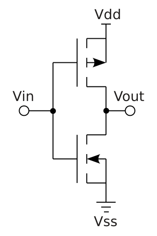
Complementary metal–oxide–semiconductor is a type of metal–oxide–semiconductor field-effect transistor (MOSFET) fabrication process that uses complementary and symmetrical pairs of p-type and n-type MOSFETs for logic functions. CMOS technology is used for constructing integrated circuit (IC) chips, including microprocessors, microcontrollers, memory chips, and other digital logic circuits. CMOS technology is also used for analog circuits such as image sensors, data converters, RF circuits, and highly integrated transceivers for many types of communication.
In automata theory, combinational logic is a type of digital logic which is implemented by Boolean circuits, where the output is a pure function of the present input only. This is in contrast to sequential logic, in which the output depends not only on the present input but also on the history of the input. In other words, sequential logic has memory while combinational logic does not.

In digital logic, an inverter or NOT gate is a logic gate which implements logical negation. It outputs a bit opposite of the bit that is put into it. The bits are typically implemented as two differing voltage levels.
In digital circuit design, register-transfer level (RTL) is a design abstraction which models a synchronous digital circuit in terms of the flow of digital signals (data) between hardware registers, and the logical operations performed on those signals.
In computer engineering, a logic family is one of two related concepts:
In computer engineering, logic synthesis is a process by which an abstract specification of desired circuit behavior, typically at register transfer level (RTL), is turned into a design implementation in terms of logic gates, typically by a computer program called a synthesis tool. Common examples of this process include synthesis of designs specified in hardware description languages, including VHDL and Verilog. Some synthesis tools generate bitstreams for programmable logic devices such as PALs or FPGAs, while others target the creation of ASICs. Logic synthesis is one step in circuit design in the electronic design automation, the others are place and route and verification and validation.
The OR gate is a digital logic gate that implements logical disjunction. The OR gate returns true if any of its inputs are true; otherwise it returns false. The input and output states are normally represented by different voltage levels.

In digital electronics, a NAND gate (NOT-AND) is a logic gate which produces an output which is false only if all its inputs are true; thus its output is complement to that of an AND gate. A LOW (0) output results only if all the inputs to the gate are HIGH (1); if any input is LOW (0), a HIGH (1) output results. A NAND gate is made using transistors and junction diodes. By De Morgan's laws, a two-input NAND gate's logic may be expressed as A • B=A+B, making a NAND gate equivalent to inverters followed by an OR gate.
XOR gate is a digital logic gate that gives a true output when the number of true inputs is odd. An XOR gate implements an exclusive or from mathematical logic; that is, a true output results if one, and only one, of the inputs to the gate is true. If both inputs are false (0/LOW) or both are true, a false output results. XOR represents the inequality function, i.e., the output is true if the inputs are not alike otherwise the output is false. A way to remember XOR is "must have one or the other but not both".
Power optimization is the use of electronic design automation tools to optimize (reduce) the power consumption of a digital design, such as that of an integrated circuit, while preserving the functionality.
The algorithmic state machine (ASM) method is a method for designing finite state machines (FSMs) originally developed by Thomas E. Osborne at the University of California, Berkeley (UCB) since 1960, introduced to and implemented at Hewlett-Packard in 1968, formalized and expanded since 1967 and written about by Christopher R. Clare since 1970. It is used to represent diagrams of digital integrated circuits. The ASM diagram is like a state diagram but more structured and, thus, easier to understand. An ASM chart is a method of describing the sequential operations of a digital system.
In integrated circuit design, dynamic logic is a design methodology in combinational logic circuits, particularly those implemented in metal–oxide–semiconductor (MOS) technology. It is distinguished from the so-called static logic by exploiting temporary storage of information in stray and gate capacitances. It was popular in the 1970s and has seen a recent resurgence in the design of high-speed digital electronics, particularly central processing units (CPUs). Dynamic logic circuits are usually faster than static counterparts and require less surface area, but are more difficult to design. Dynamic logic has a higher average rate of voltage transitions than static logic, but the capacitive loads being transitioned are smaller so the overall power consumption of dynamic logic may be higher or lower depending on various tradeoffs. When referring to a particular logic family, the dynamic adjective usually suffices to distinguish the design methodology, e.g. dynamic CMOS or dynamic SOI design.
Logic optimization is a process of finding an equivalent representation of the specified logic circuit under one or more specified constraints. This process is a part of a logic synthesis applied in digital electronics and integrated circuit design.
Low-power electronics are electronics, such as notebook processors, that have been designed to use less electric power than usual, often at some expense. In the case of notebook processors, this expense is processing power; notebook processors usually consume less power than their desktop counterparts, at the expense of lower processing power.
In electronics, pass transistor logic (PTL) describes several logic families used in the design of integrated circuits. It reduces the count of transistors used to make different logic gates, by eliminating redundant transistors. Transistors are used as switches to pass logic levels between nodes of a circuit, instead of as switches connected directly to supply voltages. This reduces the number of active devices, but has the disadvantage that the difference of the voltage between high and low logic levels decreases at each stage. Each transistor in series is less saturated at its output than at its input. If several devices are chained in series in a logic path, a conventionally constructed gate may be required to restore the signal voltage to the full value. By contrast, conventional CMOS logic switches transistors so the output connects to one of the power supply rails, so logic voltage levels in a sequential chain do not decrease. Simulation of circuits may be required to ensure adequate performance.

Glitch removal is the elimination of glitches—unnecessary signal transitions without functionality—from electronic circuits. Power dissipation of a gate occurs in two ways: static power dissipation and dynamic power dissipation. Glitch power comes under dynamic dissipation in the circuit and is directly proportional to switching activity. Glitch power dissipation is 20%–70% of total power dissipation and hence glitching should be eliminated for low power design.
State encoding assigns a unique pattern of ones and zeros to each defined state of a finite-state machine (FSM). Traditionally, design criteria for FSM synthesis were speed, area or both. Following Moore's law, with technology advancement, density and speed of integrated circuits have increased exponentially. With this, power dissipation per area has inevitably increased, which has forced designers for portable computing devices and high-speed processors to consider power dissipation as a critical parameter during design consideration.


