
A reciprocating engine, also often known as a piston engine, is typically a heat engine that uses one or more reciprocating pistons to convert high temperature and high pressure into a rotating motion. This article describes the common features of all types. The main types are: the internal combustion engine, used extensively in motor vehicles; the steam engine, the mainstay of the Industrial Revolution; and the Stirling engine for niche applications. Internal combustion engines are further classified in two ways: either a spark-ignition (SI) engine, where the spark plug initiates the combustion; or a compression-ignition (CI) engine, where the air within the cylinder is compressed, thus heating it, so that the heated air ignites fuel that is injected then or earlier.

A steam engine is a heat engine that performs mechanical work using steam as its working fluid. The steam engine uses the force produced by steam pressure to push a piston back and forth inside a cylinder. This pushing force can be transformed, by a connecting rod and crank, into rotational force for work. The term "steam engine" is most commonly applied to reciprocating engines as just described, although some authorities have also referred to the steam turbine and devices such as Hero's aeolipile as "steam engines". The essential feature of steam engines is that they are external combustion engines, where the working fluid is separated from the combustion products. The ideal thermodynamic cycle used to analyze this process is called the Rankine cycle. In general usage, the term steam engine can refer to either complete steam plants, such as railway steam locomotives and portable engines, or may refer to the piston or turbine machinery alone, as in the beam engine and stationary steam engine.

The atmospheric engine was invented by Thomas Newcomen in 1712, and is often referred to as the Newcomen fire engine or simply as a Newcomen engine. The engine was operated by condensing steam drawn into the cylinder, thereby creating a partial vacuum which allowed the atmospheric pressure to push the piston into the cylinder. It was historically significant as the first practical device to harness steam to produce mechanical work. Newcomen engines were used throughout Britain and Europe, principally to pump water out of mines. Hundreds were constructed throughout the 18th century.

The Watt steam engine design became synonymous with steam engines, and it was many years before significantly new designs began to replace the basic Watt design.

A four-strokeengine is an internal combustion (IC) engine in which the piston completes four separate strokes while turning the crankshaft. A stroke refers to the full travel of the piston along the cylinder, in either direction. The four separate strokes are termed:
- Intake: Also known as induction or suction. This stroke of the piston begins at top dead center (T.D.C.) and ends at bottom dead center (B.D.C.). In this stroke the intake valve must be in the open position while the piston pulls an air-fuel mixture into the cylinder by producing a partial vacuum in the cylinder through its downward motion.
- Compression: This stroke begins at B.D.C, or just at the end of the suction stroke, and ends at T.D.C. In this stroke the piston compresses the air-fuel mixture in preparation for ignition during the power stroke (below). Both the intake and exhaust valves are closed during this stage.
- Combustion: Also known as power or ignition. This is the start of the second revolution of the four stroke cycle. At this point the crankshaft has completed a full 360 degree revolution. While the piston is at T.D.C. the compressed air-fuel mixture is ignited by a spark plug or by heat generated by high compression, forcefully returning the piston to B.D.C. This stroke produces mechanical work from the engine to turn the crankshaft.
- Exhaust: Also known as outlet. During the exhaust stroke, the piston, once again, returns from B.D.C. to T.D.C. while the exhaust valve is open. This action expels the spent air-fuel mixture through the exhaust port.

A Stirling engine is a heat engine that is operated by the cyclic expansion and contraction of air or other gas by exposing it to different temperatures, resulting in a net conversion of heat energy to mechanical work.
A refrigerator designed to reach cryogenic temperatures is often called a cryocooler. The term is most often used for smaller systems, typically table-top size, with input powers less than about 20 kW. Some can have input powers as low as 2–3 W. Large systems, such as those used for cooling the superconducting magnets in particle accelerators are more often called cryogenic refrigerators. Their input powers can be as high as 1 MW. In most cases cryocoolers use a cryogenic fluid as the working substance and employ moving parts to cycle the fluid around a thermodynamic cycle. The fluid is typically compressed at room temperature, precooled in a heat exchanger, then expanded at some low temperature. The returning low-pressure fluid passes through the heat exchanger to precool the high-pressure fluid before entering the compressor intake. The cycle is then repeated.
The Ericsson cycle is named after inventor John Ericsson who designed and built many unique heat engines based on various thermodynamic cycles. He is credited with inventing two unique heat engine cycles and developing practical engines based on these cycles. His first cycle is now known as the closed Brayton cycle, while his second cycle is what is now called the Ericsson cycle. Ericsson is one of the few who built open-cycle engines, but he also built closed-cycle ones.

A hot air engine is any heat engine that uses the expansion and contraction of air under the influence of a temperature change to convert thermal energy into mechanical work. These engines may be based on a number of thermodynamic cycles encompassing both open cycle devices such as those of Sir George Cayley and John Ericsson and the closed cycle engine of Robert Stirling. Hot air engines are distinct from the better known internal combustion based engine and steam engine.
Cylinder head porting refers to the process of modifying the intake and exhaust ports of an internal combustion engine to improve their air flow. Cylinder heads, as manufactured, are usually suboptimal for racing applications due to being designed for maximum durability. Ports can be modified for maximum power, minimum fuel consumption, or a combination of the two, and the power delivery characteristics can be changed to suit a particular application.

This timeline of heat engine technology describes how heat engines have been known since antiquity but have been made into increasingly useful devices since the 17th century as a better understanding of the processes involved was gained. A heat engine is any system that converts heat to mechanical energy, which can then be used to do mechanical work.They continue to be developed today.

The hot-bulb engine, also known as a semi-diesel, is a type of internal combustion engine in which fuel ignites by coming in contact with a red-hot metal surface inside a bulb, followed by the introduction of air (oxygen) compressed into the hot-bulb chamber by the rising piston. There is some ignition when the fuel is introduced, but it quickly uses up the available oxygen in the bulb. Vigorous ignition takes place only when sufficient oxygen is supplied to the hot-bulb chamber on the compression stroke of the engine.
Engine efficiency of thermal engines is the relationship between the total energy contained in the fuel, and the amount of energy used to perform useful work. There are two classifications of thermal engines-
- Internal combustion and
- External combustion engines.
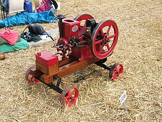
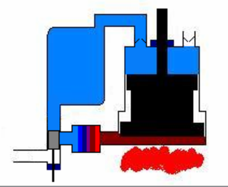
A hit-and-miss engine or Hit 'N' Miss is a type of stationary internal combustion engine that is controlled by a governor to only fire at a set speed. They are usually 4-stroke but 2-stroke versions were made. It was conceived in the late 19th century and produced by various companies from the 1890s through approximately the 1940s. The name comes from the speed control on these engines: they fire ("hit") only when operating at or below a set speed, and cycle without firing ("miss") when they exceed their set speed. This is as compared to the "throttle governed" method of speed control. The sound made when the engine is running without a load is a distinctive "Snort POP whoosh whoosh whoosh whoosh snort POP" as the engine fires and then coasts until the speed decreases and it fires again to maintain its average speed. The snorting is caused by the atmospheric intake valve used on many of these engines.
The US Rider-Ericsson Engine Company was the successor of the DeLamater Iron Works and the Rider Engine Company, having bought from both companies their extensive plants and entire stocks of engines and patterns, covering all styles of Rider and Ericsson hot air pumping engines brought out by both of the old companies since 1844, excepting the original Ericsson engine, the patterns of which were burned in the DeLameter fire of 1888.

The first recorded rudimentary steam engine was the aeolipile mentioned by Vitruvius between 30 and 15 BC and, described by Heron of Alexandria in 1st-century Roman Egypt. Several steam-powered devices were later experimented with or proposed, such as Taqi al-Din's steam jack, a steam turbine in 16th-century Ottoman Egypt, Denis Papin's working model of the steam digester in 1679 and Thomas Savery's steam pump in 17th-century England. In 1712, Thomas Newcomen's atmospheric engine became the first commercially successful engine using the principle of the piston and cylinder, which was the fundamental type of steam engine used until the early 20th century. The steam engine was used to pump water out of coal mines.

A vacuum engine refers to any kind of engine which derives its force from air pressure against one side of the piston, while also having a partial vacuum on the other side of it. This pressure differential can be the result of heat transfer, or mechanically produced by an external source.
Internal combustion engines come in a wide variety of types, but have certain family resemblances, and thus share many common types of components.
An internal combustion engine is a heat engine in which the combustion of a fuel occurs with an oxidizer in a combustion chamber that is an integral part of the working fluid flow circuit. In an internal combustion engine, the expansion of the high-temperature and high-pressure gases produced by combustion applies direct force to some component of the engine. The force is typically applied to pistons, turbine blades, a rotor, or a nozzle. This force moves the component over a distance, transforming chemical energy into kinetic energy which is used to propel, move or power whatever the engine is attached to.

The Manson engine is a hot air engine that was first described by A. D. Manson in the March 1952 issue of Newnes Practical Mechanics-Magazines. Manson engines can be started in either direction. It has a stepped piston. The front part acts as a displacer and the back part acts as a work piston. The engine only requires three moving parts: piston, piston rod, and crank.

