
Dual-tone multi-frequency signaling (DTMF) is a telecommunication signaling system using the voice-frequency band over telephone lines between telephone equipment and other communications devices and switching centers. DTMF was first developed in the Bell System in the United States, and became known under the trademark Touch-Tone for use in push-button telephones supplied to telephone customers, starting in 1963. DTMF is standardized as ITU-T Recommendation Q.23. It is also known in the UK as MF4.

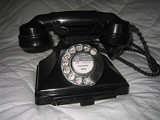
Pulse dialing is a signaling technology in telecommunications in which a direct current local loop circuit is interrupted according to a defined coding system for each signal transmitted, usually a digit. This lends the method the often used name loop disconnect dialing. In the most common variant of pulse dialing, decadic dialing, each of the ten Arabic numerals are encoded in a sequence of up to ten pulses. The most common version decodes the digits 1 through 9, as one to nine pulses, respectively, and the digit 0 as ten pulses. Historically, the most common device to produce such pulse trains is the rotary dial of the telephone, lending the technology another name, rotary dialing.
Direct distance dialing (DDD) is a telecommunication service feature in North America by which a caller may, without operator assistance, call any other user outside the local calling area. Direct dialing by subscribers typically requires extra digits to be dialed as prefixes to the directory telephone number of the destination. International Direct Distance Dialing (IDDD) extends the system beyond the geographic boundaries of the North American Numbering Plan (NANP).

In electronics and telecommunications, a crossbar switch is a collection of switches arranged in a matrix configuration. A crossbar switch has multiple input and output lines that form a crossed pattern of interconnecting lines between which a connection may be established by closing a switch located at each intersection, the elements of the matrix. Originally, a crossbar switch consisted literally of crossing metal bars that provided the input and output paths. Later implementations achieved the same switching topology in solid-state electronics. The crossbar switch is one of the principal telephone exchange architectures, together with a rotary switch, memory switch, and a crossover switch.

A blue box is an electronic device that produces tones used to generate the in-band signaling tones formerly used within the North American long-distance telephone network to send line status and called number information over voice circuits. This allowed an illicit user, referred to as a "phreaker", to place long-distance calls, without using the network's user facilities, that would be billed to another number or dismissed entirely as an incomplete call. A number of similar "color boxes" were also created to control other aspects of the phone network.
The Strowger switch is the first commercially successful electromechanical stepping switch telephone exchange system. It was developed by the Strowger Automatic Telephone Exchange Company founded in 1891 by Almon Brown Strowger. Because of its operational characteristics, it is also known as a step-by-step (SXS) switch.
4-1-1 is a telephone number for local directory assistance in Canada and the United States. Until the early 1980s, 4-1-1 and the related 1-1-3 number were free to call in most states.
The Pacific Bell Telephone Company is a telephone company that provides telephone service in California. The company is owned by AT&T through AT&T Teleholdings, and, though separate, is now marketed as “AT&T”. The company has been known by a number of names during which its service area has changed. The formal name of the company from the 1910s through the 1984 Bell System divestiture was The Pacific Telephone and Telegraph Company. As of 2002, the name “Pacific Bell” is no longer used in marketing, Pacific Bell is still the holder of record for the infrastructure of cables and fiber through much of California.
The director telephone system was a development of the Strowger or step-by-step (SXS) switching system used in London and five other large cities in the UK from the 1920s to the 1980s.
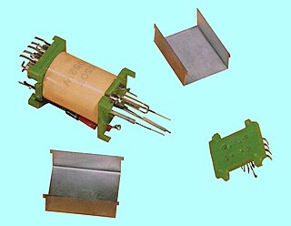
A sender was a special type of circuit in 20th-century electromechanical telephone exchanges which registered the telephone numbers dialed by the subscriber, and then transmitted that information to another exchange. In some American exchange designs, for example, the No. 1 Crossbar switch there were both originating senders and terminating senders. The corresponding device in the British director telephone system was called a "director" and, in other contexts, "register".
CLLI code is a Common Language Information Services identifier used within the North American telecommunications industry to specify the location and function of telecommunications equipment or of a relevant location such as an international border or a supporting equipment location, like a manhole or pole. Originally, they were used by Bell Telephone companies, but since all other telecommunications carriers needed to interconnect with the dominant Bell companies, CLLI code adoption eventually became universal. CLLI codes are now maintained and issued by iconectiv, which claims trademarks on the names "Common Language" and "CLLI".
In telecommunications, a long-distance call (U.S.) or trunk call is a telephone call made to a location outside a defined local calling area. Long-distance calls are typically charged a higher billing rate than local calls. The term is not necessarily synonymous with placing calls to another telephone area code.
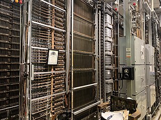
The Number Five Crossbar Switching System is a telephone switch for telephone exchanges designed by Bell Labs and manufactured by Western Electric starting in 1947. It was used in the Bell System principally as a Class 5 telephone switch in the public switched telephone network (PSTN) until the early 1990s, when it was replaced with electronic switching systems. Variants were used as combined Class 4 and Class 5 systems in rural areas, and as a TWX switch.
The Number One Crossbar Switching System (1XB), was the primary technology for urban telephone exchanges served by the Bell System in the mid-20th century. Its switch fabric used the electromechanical crossbar switch to implement the topology of the panel switching system of the 1920s. The first No. 1 Crossbar was installed in the PResident-2 central office at Troy Avenue in Brooklyn, New York which became operational in February 1938.
The Number One Electronic Switching System (1ESS) was the first large-scale stored program control (SPC) telephone exchange or electronic switching system in the Bell System. It was manufactured by Western Electric and first placed into service in Succasunna, New Jersey, in May 1965. The switching fabric was composed of a reed relay matrix controlled by wire spring relays which in turn were controlled by a central processing unit (CPU).
TXE, was a family of telephone exchanges developed by the British General Post Office (GPO), designed to replace the ageing Strowger switches.
The original North American area codes were established by the American Telephone and Telegraph Company (AT&T) in 1947, following the demonstration of regional Operator Toll Dialing during the World War II period. The program had the goal of speeding the connecting times for long-distance calling by eliminating intermediary telephone operators. Expanding this technology for national use required a comprehensive and universal, continent-wide telephone numbering plan.

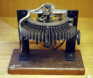
The push-button telephone is a telephone that has buttons or keys for dialing a telephone number, in contrast to having a rotary dial as in earlier telephone instruments.

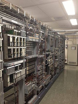
A telephone exchange, telephone switch, or central office is a telecommunications system used in the public switched telephone network (PSTN) or in large enterprises. It interconnects telephone subscriber lines or virtual circuits of digital systems to establish telephone calls between subscribers.
The Panel Machine Switching System is a type of automatic telephone exchange for urban service that was used in the Bell System in the United States for seven decades. The first semi-mechanical types of this design were installed in 1915 in Newark, New Jersey, and the last were retired in the same city in 1983.
