
An ammeter is an instrument used to measure the current in a circuit. Electric currents are measured in amperes (A), hence the name. For direct measurement, the ammeter is connected in series with the circuit in which the current is to be measured. An ammeter usually has low resistance so that it does not cause a significant voltage drop in the circuit being measured.
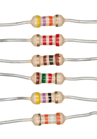
A resistor is a passive two-terminal electrical component that implements electrical resistance as a circuit element. In electronic circuits, resistors are used to reduce current flow, adjust signal levels, to divide voltages, bias active elements, and terminate transmission lines, among other uses. High-power resistors that can dissipate many watts of electrical power as heat may be used as part of motor controls, in power distribution systems, or as test loads for generators. Fixed resistors have resistances that only change slightly with temperature, time or operating voltage. Variable resistors can be used to adjust circuit elements, or as sensing devices for heat, light, humidity, force, or chemical activity.
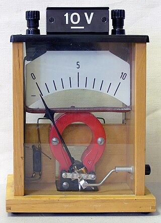
A voltmeter is an instrument used for measuring electric potential difference between two points in an electric circuit. It is connected in parallel. It usually has a high resistance so that it takes negligible current from the circuit.
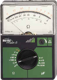
An ohmmeter is an electrical instrument that measures electrical resistance. Multimeters also function as ohmmeters when in resistance-measuring mode. An ohmmeter applies current to the circuit or component whose resistance is to be measured. It then measures the resulting voltage and calculates the resistance using Ohm’s law .
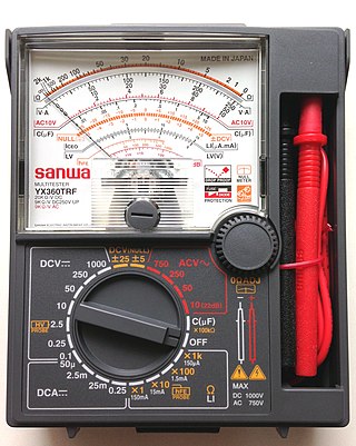
A multimeter is a measuring instrument that can measure multiple electrical properties. A typical multimeter can measure voltage, resistance, and current, in which case can be used as a voltmeter, ohmmeter, and ammeter. Some feature the measurement of additional properties such as temperature and capacitance.

Ohm's law states that the electric current through a conductor between two points is directly proportional to the voltage across the two points. Introducing the constant of proportionality, the resistance, one arrives at the three mathematical equations used to describe this relationship:

A short circuit is an electrical circuit that allows a current to travel along an unintended path with no or very low electrical impedance. This results in an excessive current flowing through the circuit. The opposite of a short circuit is an open circuit, which is an infinite resistance between two nodes.

Electronic test equipment is used to create signals and capture responses from electronic devices under test (DUTs). In this way, the proper operation of the DUT can be proven or faults in the device can be traced. Use of electronic test equipment is essential to any serious work on electronics systems.
In electronics, a continuity test is the checking of an electric circuit to see if current flows . A continuity test is performed by placing a small voltage across the chosen path. If electron flow is inhibited by broken conductors, damaged components, or excessive resistance, the circuit is "open".

Transistor testers are instruments for testing the electrical behavior of transistors and solid-state diodes.

A continuity tester is an item of electrical test equipment used to determine if an electrical path can be established between two points; that is if an electrical circuit can be made. The circuit under test is completely de-energized prior to connecting the apparatus.

A test probe is a physical device used to connect electronic test equipment to a device under test (DUT). Test probes range from very simple, robust devices to complex probes that are sophisticated, expensive, and fragile. Specific types include test prods, oscilloscope probes and current probes. A test probe is often supplied as a test lead, which includes the probe, cable and terminating connector.

In electrical safety testing, portable appliance testing is a process by which electrical appliances are routinely checked for safety, commonly used in the United Kingdom, Ireland, New Zealand and Australia. The formal term for the process is "in-service inspection & testing of electrical equipment". Testing involves a visual inspection of the equipment and verification that power cables are in good condition. Additionally, other tests may be done when required, such as a verification of earthing (grounding) continuity, a test of the soundness of insulation between the current-carrying parts, and a check for any exposed metal that could be touched. The formal limits for a pass/fail of these electrical tests vary somewhat depending on the category of equipment being tested.
In copper twisted pair wire networks, copper cable certification is achieved through a thorough series of tests in accordance with Telecommunications Industry Association (TIA) or International Organization for Standardization (ISO) standards. These tests are done using a certification-testing tool, which provide pass or fail information. While certification can be performed by the owner of the network, certification is primarily done by datacom contractors. It is this certification that allows the contractors to warranty their work.
In electrical engineering, electrical safety testing is essential to make sure electrical products and installations are safe. To meet this goal, governments and various technical bodies have developed electrical safety standards. All countries have their own electrical safety standards that must be complied with. To meet to these standards, electrical products and installations must pass electrical safety tests.

An electrical outlet tester, receptacle tester, or socket tester is a small device containing a 3-prong power plug and three indicator lights, used for quickly detecting some types of incorrectly-wired electrical wall outlets or campsite supplies.

A Megohmmeter or insulation resistance tester, is a special type of ohmmeter used to measure the electrical resistance of insulators. Insulating components, for example cable jackets, must be tested for their insulation strength at the time of commissioning and as part of maintenance of high voltage electrical equipment and installations.

A tube tester is an electronic instrument designed to test certain characteristics of vacuum tubes. Tube testers evolved along with the vacuum tube to satisfy the demands of the time, and their evolution ended with the tube era. The first tube testers were simple units designed for specific tubes to be used in the battlefields of World War I by radio operators, so they could easily test the tubes of their communication equipment.

Megger Group Limited is a British manufacturing company that manufactures electronic test equipment and measuring instruments for electrical power applications.

A grounding resistance tester also called an earth tester is a soil resistance measuring instrument. It is used for sizing and projecting grounding grids.